Showing posts with label radio amateur. Show all posts

Tuesday, 11 September 2012

RAQI Press Release :: Amendment to the Ban of Cellular Telephone Use While Driving

Communiqué 2012-03 – Amendment to the Ban of Cellular Telephone Use While Driving

The ban on the use of cellular telephones while driving came into force in April 2008. Since that time different police departments have issued tickets for the use of various types of devices which could be construed as telephone systems. Those who have received these tickets have vigorously contested them. The courts which have heard these cases have expanded considerably on the meaning of the law to include a multitude of communications equipment far from being cellular telephones.

RAQI has periodically made representations to various government authorities with a view to excluding amateur radio equipment from the ban on the use of cellular telephones while driving. On different occasions such as the RAQI nets or when meeting with club members RAQI has explained that the SAAQ and the Ministry of Transport were waiting to see in which direction the courts would interpret the cellular telephone law.

RAQI has also pointed out that radio amateurs are not the only group affected by the wider interpretation of the courts. For example, among others, the Ministry of Transport itself, Hydro Québec and many others cannot use their radio communications equipment in their own vehicles.

After four years of uncertainty the situation has now been clarified by amendments to the Highway Safety Code which came into effect this past June 6. The new article 439.1 of the code reads as follows:

439.1. No person may, while driving a road vehicle, use a hand-held device that includes a telephone function.

For the purposes of this section, a driver who is holding a hand-held device that includes a telephone function is presumed to be using the device.

This prohibition does not apply to drivers of emergency vehicles in the performance of their duties.

The first paragraph does not apply to a two-way radio, that is to say a cordless voice communication device which does not allow the parties to speak simultaneously.

The Minister may, by order, determine other situations or types of devices to which the prohibition set out in the first paragraph does not apply.

The underlined text is the two paragraphs added on June 6, 2012.

The legislature has retained the spirit of the 2008 law to prevent the use of cellular telephones by the general public while driving without restricting those using radio communications systems which were already in use before the arrival of cellular telephones, such as amateur radio.

RAQI is proud to have contributed, by its representations to the authorities concerned, to the clarification of the text of the law banning the use of cellular telephones while driving and permitting ALL QUEBEC RADIOAMATEURS and not just members of RAQI to continue to use their mobile communications equipment in their vehicles as they always have.

RAQI hopes that the radio amateur community recognizes the importance of a strong provincial association and the support it provides.
(30)

Source: http://raqi.ca/node/278

Links:
The Quebec Highway Safety Code (EN)
Download a printable version of the amendments in PDF format (FR/EN)

Tuesday, 3 July 2012

Low power computing platforms for amateur radio :: by Bruce Given VE2GZI

There has been a explosion of cheap and powerful computing platforms appearing in the hobbyist/maker market in the last year.

While these boards can be used in a myriad of digital applications for amateur radio, the purpose of this article is take a quick look at what is out there, to plant some seeds and get the creativeness flowing...

All of these boards run a version of the Linux operations system which is a free Unix like operating system it has a number of advantages over the Microsoft based offerings.

  • It’s free !
  • Posix compliance (reacts to real time events better than windows)
  • Large community support
  • Open source ( Code is open to scrutiny and can be modified for your needs )
  • Complete software development suites in most languages (C++, Java, .Net etc… )
  • Can be configured for a nice graphical interface or Command line interface

Let’s take a look at what’s out there!

I will be ignoring the both the Panda board and the Beagle boards as these are targeted to more of a development environment or are more expensive.

Let`s start with the board that’s creating a lot of buzz

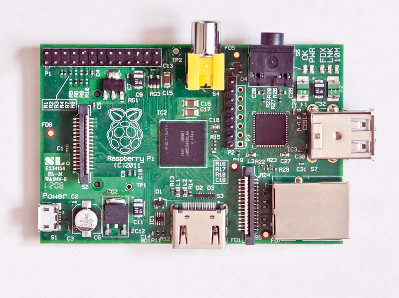
Raspberry Pi [www.raspberrypi.org]
Price: $35.00
Based on the Broadcomm BCM2835 System on a chip.

•    ARM 11 running at 700 MHz processor,
•    Video GPU
•    256 Megabytes of Ram ( Can’t be upgraded)
•    2 USB 2.0 ports
•    HDMI and Composite Video outputs
•    10/100 Ethernet RJ-45 Jack
•    SD Card socket
•    8 × GPIO, UART, I²C bus, SPI bus with two chip selects, +3.3 V, +5 V, ground
•    Audio output from HDMI as well from a standard 3.5mm jack

All in a board 85.60mm x 53.98mm x 17mm.

Current operating systems for this are Debian GNU/Linux, Fedora, Arch Linux ARM, all of these are available on the web so all you have to download them copy them to the SD card and boot the Pi from the SD and you are up and running with a Graphical Linux Operating system.

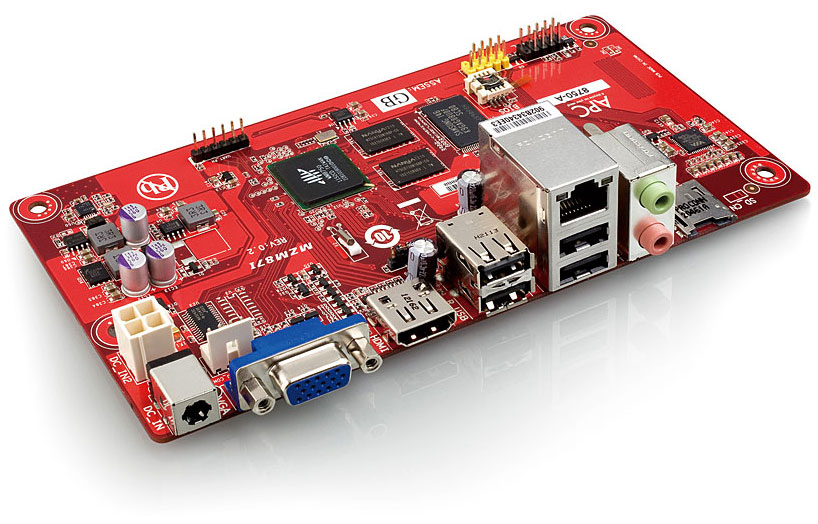
APC [www.apc.io]
Price:  $49.00
Based on the Via’s Wondermedia  WM8750 System On a Chip

•    ARM 11 running at 800 MHz processor,
•    Video GPU
•    512 Megabytes of Ram ( Can’t be upgraded)
•    4 USB 2.0 ports
•    HDMI and VGA Video outputs
•    10/100 Ethernet RJ-45 Jack
•    MicroSD Card socket
•    Audio output/Input from a standard 3.5mm jack

All this in 170 x 85mm package, this is the NEO-ITX standard which is compatible with Mini-ITX and MicroATX  (this means it will fit in a MicroATX/Mini-ITX PC case).

Currently the only operating system for this is Android 2.3 which ships with it (pretty sure that within a couple of months that there will be a couple of flavors of Linux available for it)

OK, so we have the platforms what are we going to do with them? Well let’s see what some of our fellow hams have started to do …

John Hays of NW Digital radio has successfully downloaded and run Jonathan Naylor’s (G4KLX)         GMSK Repeater and IrcDDB Gateway software on the Raspberry Pi  and there is a D-Star repeater LD1XI in Norway that is now running on the Raspberry Pi connected to the DVRPTR.

The code was even complied on the Raspberry Pi; the OS is Debian "Squeeze" beta. IrcDDBgateway  and DVRPTR repeater run at 10-11% CPU each when active.

Although the APC, which has a little more computing power maybe a better choice, having a D-Star hotspot for the price of the GMSK board and a Raspberry Pi, that’s pretty cool! You are no longer using a PC as the controller.

Expanding on the D-Star hotspot: how about a portable, solar powered, D-Star hotspot based on a APC or Raspberry Pi, with a wireless USB adapter, a GMSK Modem board? Paired with a AMBE codec board it could enable a standard radio to become a D-star radio on any frequency (220mhz, HF,  whatever you'd like...)

Another application for these low power computing platforms could be a controller for a SDR ( Software Defined  Radio). But,  that is a topic that we will get on to on a future article.

Conclusion

By combining digital radio with small form factor, low cost computing platforms and open source free software we have a great recipe for experimentation and a way of getting younger internet savvy  people back into the hobby.

I hope that I have given you a quick look at some of the exciting things that are coming our way and if I can be of any help or if you just want to ask questions you can find me at bruce.given@gmail.com

73, Bruce VE2GZI

Sunday, 10 June 2012

My Modular Approach To HF Digital Interfacing :: by Steve Perron VA2PSL


While I do have another interface I built a few years back on a PC board with isolation transformers, RS232 to PTT, VOX PTT and even a sound card to Morse keying interface, I prefer to use a more modular approach to interfacing HF transceivers to a sound card to use the various digital modes. Because getting on HF digital has been as simple as hooking up your transceiver to the sound card of your computer, there's been a wide range of new applications and modes available to experiment with over the past decade. I started playing around with PSK31 when it came out in the late 90s, and my first interface was a simple cable from my sound card to the back of my Icom 735, no audio isolation. I also used an RS232 to PTT that was made with a resistor and the perennial 2N2222a. It worked great, so keep this in mind.
Now, my current little HF rig, the FT-857 is not as simple to interface as some of the newer rigs like the Icom 7200 or the Kenwood TS590 which have built-in USB sound card and radio control, but it does provide a lot more functionality than my old 735. For starters, the radio has settings for audio gain when running digital, aka the back input/output on the rig. There's also a digital VOX and PTT through the CAT interface.

Part 1: The USB Serial Cable

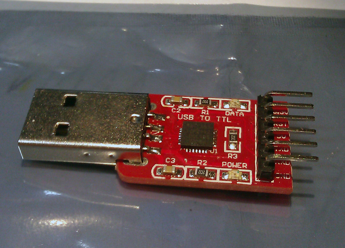
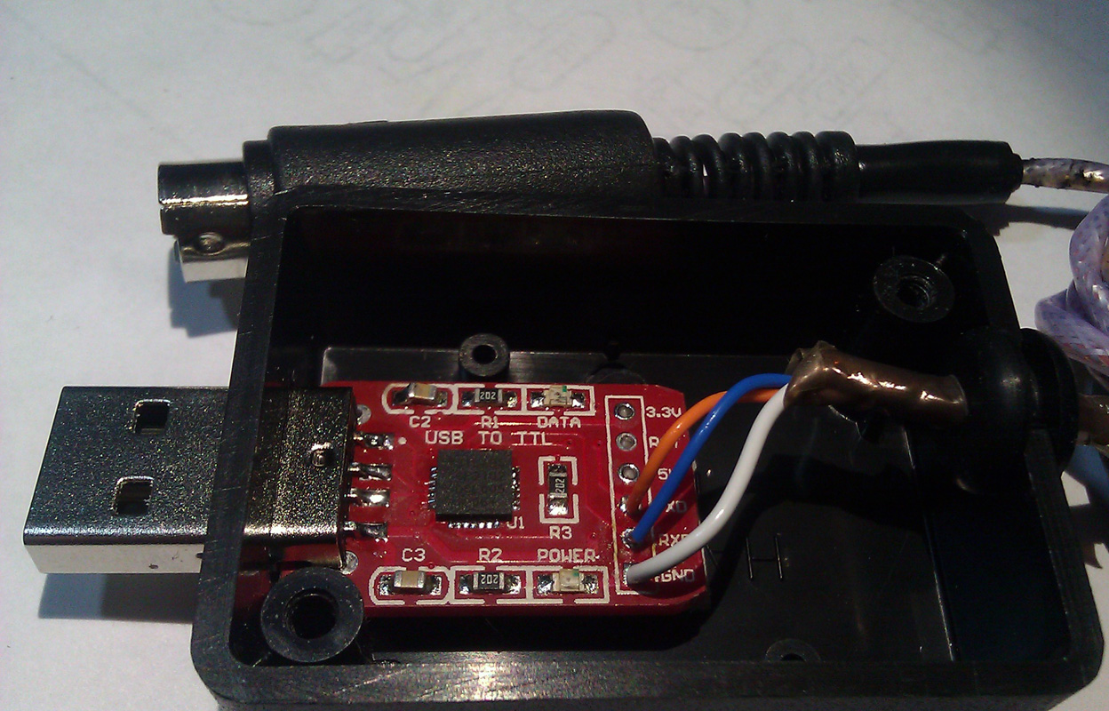
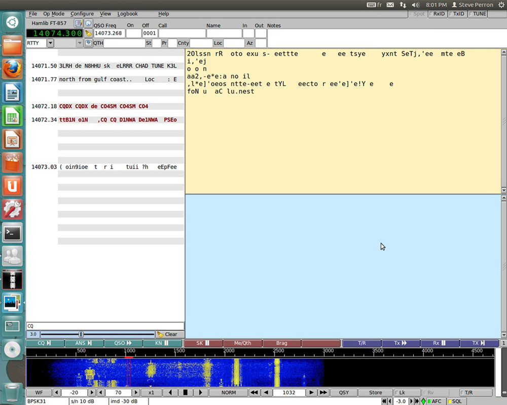
Almost all transceivers made since the mid 80s have some form of serial port interface which provide for the control of the mode, frequency, PTT and on the newer rigs, a lot more. If you've played with Ham Radio Deluxe, you actually get a pretty complete panel to control your radio. Most plans you'll find online or in the magazines are simple RS232 voltage converters (+12V to -12V) to TTL (0V to +5V). You can order USB cables from various sources, but they tend to use the Prolific PL2303 chip which has been cloned by Chinese chip manufacturers. Prolific has added an anti-clone feature in their drivers which is why all these USB programming cables from China do not work with the latest drivers. I had a CAT (Yaesu's name for this interface) USB cable with the PL2303 clone, and it simply died on me. My new interface uses the CP2102 from Silicon labs. The drivers actually work, and you can pick up the ready-made modules on eBay for less than 3$. As I said earlier, quite a few software support the PTT functionality directly through this interface, including my favorite software, FLDIGI. FLDIGI is available on most operating systems, including Linux. So when running FLDIGI, I get both the control of the mode/frequency and the PTT using my simple USB to CAT interface. See the pictures below. All that is required on the Yaesu and Kenwood is for the RX/TX and GND to be connected to the connector on the back of the transceiver. If you're using an Icom transceiver, the RX and TX would be tied together, since the interface is half-duplex. My module did not follow the convention of RX->TX, TX->RX, but rather RX->RX and TX->TX, so please be aware. If it's not working for you, simply swap the wires around. In windows, the interface will be assigned a Com port. Under Linux, it will be /dev/ttyUSB0, when the 0 could be a different number if like me you have more than one USB-Serial cable attached.

Part 2: The Sound card Interface


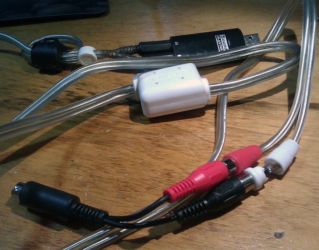
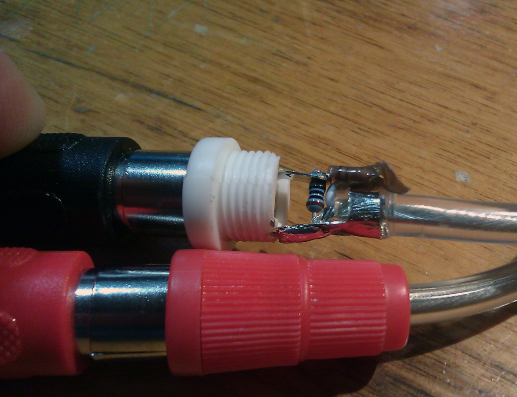
My audio interface is even simpler. I simply used half of an audio cable with female RCA jacks soldered to a mini-din8 on the ground, Audio in and Audio Out pins. I'm later going to add another RCA jack for the PTT line. My other cable is an eBay-special Griffin stereo isolation cable. While this cable is not available anymore, any similar cable/interface could be used. I installed 3.5mm stereo plugs on one end, and I replaced the male RCA on the other end so that I could make a simple voltage divider to reduce the audio amplitude of the signal so it would be more compatible with most transceivers out there. It's not required on the FT857 thanks to the programmable audio gain, but I want my cable to be compatible with most rigs. The voltage divider is simply two resistors, 10k and 1k, soldered inside the RCA jack going to the audio in of the transceiver. You can see that I'm also using a USB sound card. This is mostly to avoid transmitting operating system sounds and some laptops lack any form of audio input.


Part 3: The Optional RS232 PTT Interface

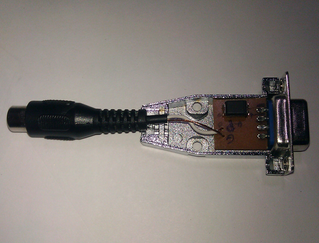
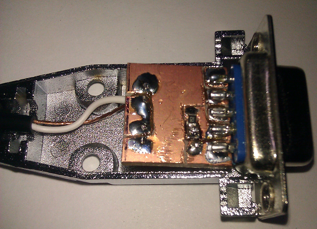
This interface is simply an opto-isolator inside a DB9 housing. It can be used with any serial port, including most USB-Serial cables. The CP2102 module I discussed earlier lacks the required RTS or DTR signals. To keep the little PCB as simple as possible, I only use the DTR. The PCB was done freehand using a Dremel tool. You can find the schematic of the interface online or even in the ARRL handbook. This interface would be required if the software does not support CAT PTT, VOX is not available or undesirable. An example of this would be when running the UZ7HO sound card packet modem. There are numerous amateurs using APRS on HF with this modem. Alternatively, it could also be used as a software Morse keyer. N1MM and other logging software support this as well as the CW-daemon in Linux.


Part 4: Digital Modes Software and Random Ramblings

There are a few software I find more interesting. FLDIGI is the Swiss army-knife of digital modes. I'm only aware of one software that supports more different modes, MultiPSK, but I find it not user-friendly and it does not run on Linux. PSK Mail is a software than runs of top of FLDIGI and provides ARQ email throughout the world (Think Amtor, Pactor). Winmor is a modem that can be used with RMS Express to provide access to the Winlink 2000 system without an expensive SCS-PTC Pactor modem. While I would not rely on Winmor to do mission-critical emails, it can be useful to check your emails if you're in an area that does not have any other forms of coverage. Winmor is only available on Windows.
I don't recommend using the microphone jack unless your rig only has this input. The microphone jack has much more gain than the digital port at the back of your radio and this can lead to over-modulation. Most commercially made interfaces simply regroup all these functionalities in a pretty box. The wildly popular Signalink interface from Tigertronics is a USB soundcard with audio isolation and a VOX setup. The VOX would be redundant on my transceiver, and I prefer not to use VOX, as it tends to mangle most ARQ modes, like HF packet. The first few milliseconds of the transmission would be missing because VOX always has latency.

Saturday, 3 March 2012

Curtain Antenna for HF


The curtain antenna is a dipole array, consisting of rows and columns of dipoles. The number of rows can be 1, 2, 3, 4 or 6; the number of columns is usually 2 or 4.

The curtain antenna is a high gain directional antenna, designed for medium and long range communications.

The dipoles are horizontally polarized and a reflector screen is placed behind the dipole array to provide a directive beam.

Curtain antennas are available in two sizes. A low-band array covers the 6, 7, 9 and 11 MHz bands and a high-band array covers the 11, 13, 15, 17 and 21 MHz bands (or 13-26 MHz bands).

The number of dipole columns defines the azimuth beamwidth. For a 2-wide dipole array, the beamwidth is around 50°, for a 4-wide dipole array around 30°. The main beam can be slewed by 15 or 30° so that a maximum coverage of 90° can be achieved.

The number of dipole rows and the height of the lowest element above ground determine the elevation angle and consequently the distance of the service area. A 2-row high array has a typical takeoff angle of 20° and is used for medium range communications, while a 4-row high array has a typical takeoff angle of 10° and is used for long range communications.

The curtain antenna is designed for connection to a 300 ohm balanced open wire feeder.


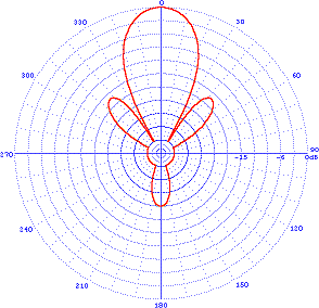
Azimuth pattern
Elevation pattern

Technical Specifications
Azimuth pattern: directional
Frequency ranges: 6-26 MHz, up to 6 adjacent SW bands
Gain: 12.5-22.5 dBi
Input impedance: 300 ohm balanced
Polarization: horizontal
Power ratings: up to 500 kW carrier with 100% modulation

Tree Mounted HF Ground Plane Antenna

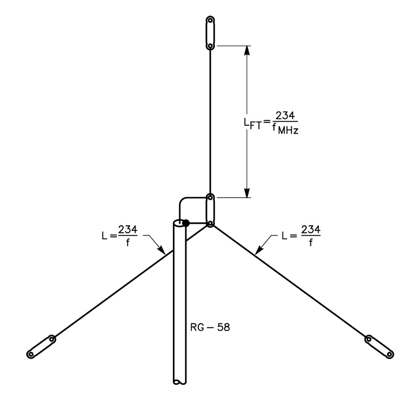
A tree-mounted, vertically polarized antenna may not be your first choice. Most engineering references do not recommend it, but such an antenna does not cost much, is inconspicuous, and it works.
The idea was described by Chuck Hutchinson, K8CH, in QST for September 1984.

The antenna itself is simple. A piece of RG-58 cable runs to the feed point of the antenna, and is attached to an insulator. Two radial wires are soldered to the coax-line braid at this point. Another piece of wire forms the radiator.

The top of the radiator section is suspended from a tree limb or other convenient support, and in turn supports the rest of the antenna. The dimensions for the antenna are given in the image (click on it to enlarge).

All three wires of the antenna are ¼ wavelength long. This generally limits the usefulness of the antenna for portable operation to 7 MHz and higher bands, as temporary supports higher than 35 or 40 feet are difficult to
come by.

Satisfactory operation might be had on 3.5 MHz with an inverted-L configuration of the radiator, if you can overcome the accompanying difficulty of erecting the antenna at the operating site.

The tree-mounted vertical idea can also be used for fixed station installations to make an invisible antenna.

Sunday, 29 January 2012

REPEATER SYSTEMS : Cavity resonators and duplexers

Cavity Resonators

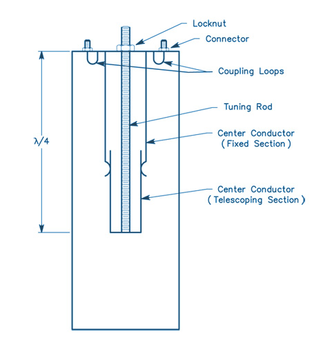
Receiver desensing can be reduced by separating the transmitter and receiver antennas. But the amount of transmitted energy that reaches the receiver input must often be decreased even farther. Other nearby transmitters can cause desensing as well. A cavity resonator (cavity filter) can be helpful in solving these problems.

When properly designed and constructed, this type of resonator has very high Q. A cavity resonator placed in series with a transmission line acts as a band-pass filter. For a resonator to operate in series, it must have input and output coupling loops (or probes). A cavity resonator can also be connected across (in parallel with) a transmission line. The cavity then acts as a band-reject (notch) filter, greatly attenuating energy at the frequency to which it is tuned.

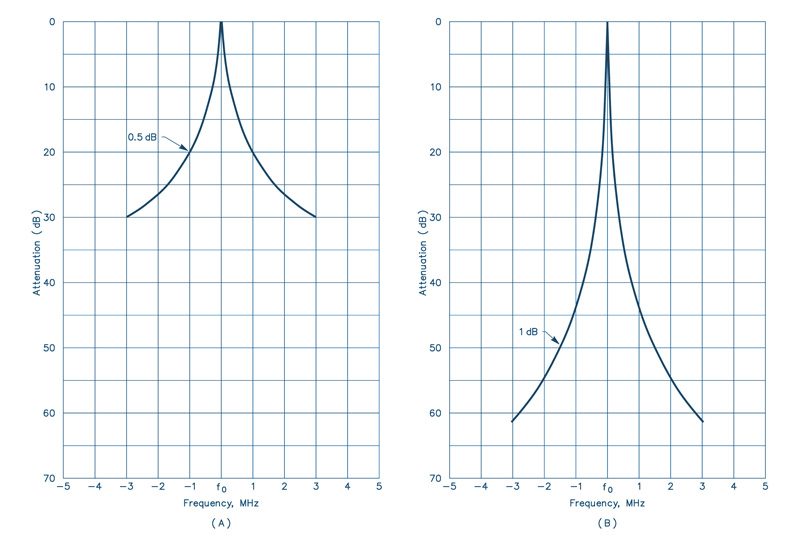
Only one coupling loop or probe is required for this method of filtering. This type of cavity could be used in the receiver line to "notch" the transmitter signal. Several cavities can be connected in series or parallel to increase the attenuation in a given configuration. The diagram below show the attenuation of a single cavity (A) and a pair of cavities (B).

The only situation in which cavity filters would not help is the case where the off-frequency noise of the transmitter was right on the receiver frequency. With cavity resonators, an important point to remember is that addition of a cavity across a transmission line may change the impedance of the system. This change can be compensated by adding tuning stubs along the transmission line.


Duplexers

Most amateur repeaters in the 144, 220 and 440 MHz bands use duplexers to obtain the necessary transmitter to receiver isolation. Duplexers have been commonly used in commercial repeaters for many years.

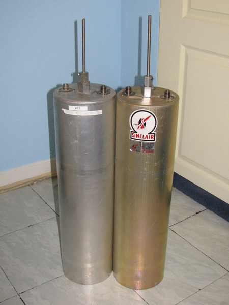
The duplexer consists of two high-Q filters. One filter is used in the feed line from the transmitter to the antenna, and another between the antenna and the receiver. These filters must have low loss at the frequency to which they are tuned while having very high attenuation at the surrounding frequencies. To meet the high attenuation requirements at frequencies within as little as 0.4% of the frequency to which they are tuned, the filters usually take the form of cascaded transmission line cavity filters.

These are either band-pass filters, or band-pass filters with a rejection notch which is tuned to the center frequency of the other filter. The number of cascaded filter sections is determined by the frequency separation and the ultimate attenuation requirements.

Duplexers for the amateur bands represent a significant technical challenge, because in most cases amateur repeaters operate with significantly less frequency separation than their commercial counterparts. Many manufacturers market high quality duplexers for the amateur frequencies.

Duplexers consist of very high-Q cavities whose resonant frequencies are determined by mechanical components, in particular the tuning rod. The rod is usually made of a material that has a limited thermal expansion coefficient (such as Invar). Detuning of the cavity by environmental changes introduces unwanted losses in the antenna system.

These can be broken into four major categories:
  • Ambient temperature variation (which leads to mechanical variations related to the thermal expansion coefficients of the materials used in the cavity).
  • Humidity (dielectric constant) variation.
  • Localized heating from the power dissipated in the cavity (resulting from its insertion loss).
  • Mechanical variations resulting from other factors (vibration, etc).

In addition, because of the high-Q nature of these cavities, the insertion loss of the duplexer increases when the signal is not at the peak of the filter response. This means, in practical terms, that less power is radiated for a given transmitter output power.

Also, the drift in cavities in the receiver line results in increased system noise figure, reducing the sensitivity of the repeater. As the frequency separation between the receiver and the transmitter decreases, the insertion loss of the duplexer reaches certain practical limits. At 144 MHz, the minimum insertion loss for 600 kHz spacing is 1.5 dB per filter.

Testing and using duplexers requires some special considerations (especially as frequency increases). Because duplexers are very high-Q devices, they are very sensitive to the termination impedances at their ports. A high SWR on any port is a serious problem, because the apparent insertion loss of the duplexer will increase, and the isolation may appear to decrease. Some have found that when duplexers are used at the limits of their isolation capabilities, a small change in antenna SWR is enough to cause receiver desensitization. This occurs most often under ice-loading conditions on antennas with open-wire phasing sections.

The choice of connectors in the duplexer system is important. BNC connectors are good for use below 300 MHz. Above 300 MHz, their use is discouraged because even though many types of BNC connectors work well up to 1 GHz, older style standard BNC connectors are inadequate at UHF and above.

Type N connectors should be used above 300 MHz. It is false economy to use marginal quality connectors. Some commercial users have reported deteriorated isolation in commercial UHF repeaters when using such connectors. The location of a bad connector in a system is a complicated and frustrating process. Despite all these considerations, the duplexer is still the best method for obtaining isolation in the 144 - 925 MHz range.

Source: the ARRL Antenna Handbook

Thursday, 19 January 2012

Electra Proximity Payload :: SDR ( software-defined radio) by NASA's Jet Propulsion Laboratory

Today, I stumbled upon a little SDR (software-defined radio) package with a big responsibility.

Electra Proximity Payload, is a software-defined radio defined and implemented by the Jet Propulsion Laboratory for use between spacecraft. It is typically used by a lander to communicate with an orbiter that can then communicate with Earth.

Click here to download the complete specifications in PDF format

Sources: Wikipedia and NASA

Sunday, 15 January 2012

The J-Pole Antenna

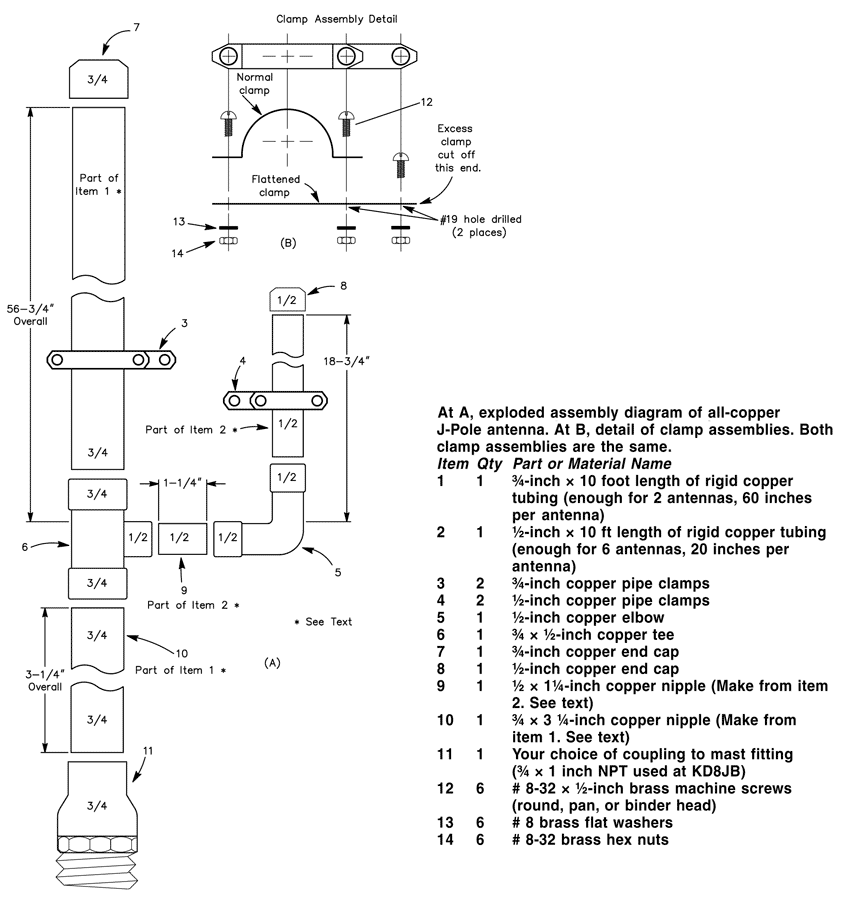
Click on the image to enlarge it
The J-Pole is a half-wave antenna that is end-fed at its bottom. Since the radiator is longer than that of a 1/4-wave ground-plane antenna, the vertical lobe is compressed down toward the horizon and it has about 1.5 dB of gain compared to the ground-plane configuration.

The stub-matching section used to transform the high impedance seen looking into a half-wave to 50 Ω coax is shorted at the bottom, making the antenna look like the letter “J,” and giving the antenna its name.  Rigid copper tubing, fittings and assorted hardware can be used to make a really rugged J-pole antenna for 2 meters. When copper tubing is used, the entire assembly can be soldered together, ensuring electrical integrity, and making the whole antenna weatherproof.

No special hardware or machined parts are used in this antenna, nor are insulating materials needed, since the antenna is always at dc ground. Best of all, even if the parts aren’t on sale, the antenna can be built for less than $15. If you only build one antenna, you’ll have enough tubing left over to make most of a second antenna.

Construction
Copper and brass is used exclusively in this antenna. These metals get along together, so dissimilar metal corrosion is eliminated. Both metals solder well, too.

Cut the copper tubing to the lengths indicated. Item 9 is a 11/4-inch nipple cut from the 20-inch length of 1/2-inch tubing. This leaves 183/4 inches for the 1/4-matching stub. Item 10 is a 31/4-inch long nipple cut from the 60-inch length of 3/4-inch tubing. The 3/4-wave element should measure 563/4-inches long.

Remove burrs from the ends of the tubing after cutting, and clean the mating surfaces with sandpaper, steel wool, or emery cloth. After cleaning, apply a very thin coat of flux to the mating elements and assemble the tubing, elbow, tee, end caps and stubs. Solder the assembled parts with a propane torch and rosin-core solder. Wipe off excess solder with a damp cloth, being careful not to burn yourself.

The copper tubing will hold heat for a long time after you’ve finished soldering. After soldering, set the assembly aside to cool. Flatten one each of the 1/2-inch and 3/4-inch pipe clamps. Drill a hole in the flattened clamp as shown. Assemble the clamps and cut off the excess metal from the flattened clamp using the unmodified clamp as a template. Disassemble the clamps. Assemble the 1/2-inch clamp around the 1/4-wave element and secure with two of the screws, washers, and nuts as shown. Do the same with the 3/4-inch clamp around the 3/4-wave element. Set the clamps initially to a spot about 4 inches above the bottom of the “J” on their respective elements. Tighten the clamps only finger tight, since you’ll need to move them when tuning.

Tuning
The J-Pole can be fed directly from 50-ohm coax through a choke balun (3 turns of the feed coax rolled into a coil about 8 inches in diameter and held together with electrical tape). Before tuning, mount the antenna vertically, about 5 to 10 feet from the ground. A short TV mast on a tripod works well for this purpose.

When tuning VHF antennas, keep in mind that they are sensitive to nearby objects—such as your body. Attach the feed line to the clamps on the antenna, and make sure all the nuts and screws are at least finger tight. It really doesn’t matter to which element (¾-wave element or stub) you attach the coaxial center lead.

Tune the antenna by moving the two feed-point clamps equal distances a small amount each time until the SWR is minimum at the desired frequency. The SWR will be close to 1:1.

Final Assembly
The final assembly of the antenna will determine its long-term survivability. Perform the following steps with care. After adjusting the clamps for minimum SWR, mark the clamp positions with a pencil and then remove the feed line and clamps. Apply a very thin coating of flux to the inside of the clamp and the corresponding surface of the antenna element where the clamp attaches. Install the clamps and tighten the clamp screws.

Solder the feed line clamps where they are attached to the antenna elements. Now, apply a small amount of solder around the screw heads and nuts where they contact the clamps. Don’t get solder on the screw threads! Clean away excess flux with a non-corrosive solvent.

After final assembly and erecting/mounting the antenna in the desired location, attach the feed line and secure with the remaining washer and nut. Weather-seal this joint with RTV.

Source: The ARRL Antenna Handbook

Saturday, 7 January 2012

The G5RV Multiband HF Antenna

A multiband antenna that does not require a lot of space, is simple to construct, and is low in cost is the G5RV.

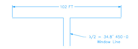
Designed in England by Louis Varney (G5RV) some years ago, it has become quite popular in the US. The G5RV design is shown in Fig 8. The antenna may be used from 3.5 through 30 MHz. Although some amateurs claim it may be fed directly with 50-Ω coax on several amateur bands with a low SWR, Varney himself recommended the use of an antenna tuner on bands other than 14 MHz. In fact, an analysis of the G5RV feed-point impedance shows there is no length of balanced line of any characteristic impedance that will transform the terminal impedance to the 50 to 75-Ω range on all bands. (Low SWR indication with coax feed and no matching network on bands other than 14 MHz may indicate excessive losses in the coaxial line.)

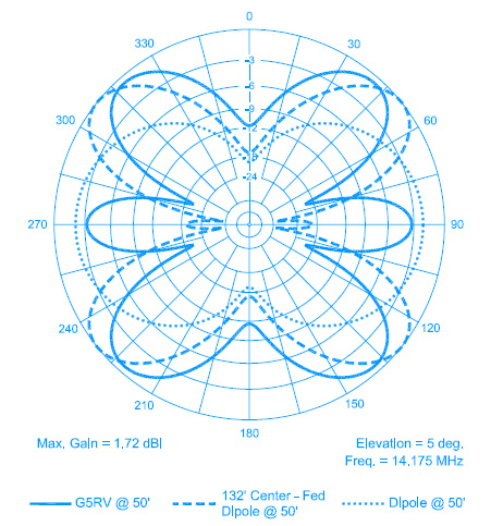
Fig 2 shows the 20-meter azimuthal pattern for a G5RV at a height of 50 feet over fl at ground, at an elevation angle of 5° that is suitable for DX work. For comparison, the response for two other antennas is also shown in Fig 2—a standard half wave 20-meter dipole at 50 feet and a 132-foot long center-fed dipole at 50 feet.

The G5RV on 20 meters is, of course, longer than a standard half wave dipole and it exhibits about 2 dB more gain compared to that dipole. With four lobes making it look rather like a four-leaf clover, the azimuth pattern is more omni directional than the two-lobed dipole. The 132-foot center-fed dipole is longer than the G5RV and it has about 0.5 dB more gain than the G5RV, also exhibiting four major lobes, along with two strong minor lobes in the plane of the wire. Overall, the azimuthal response for the G5RV is more omni directional than the comparison antennas.

The G5RV patterns for other frequencies are similar to those shown for the 135-foot dipole previously for other frequencies. Incidentally, you may be wondering why a 132-foot dipole is shown in Fig 2, rather than the 135-foot dipole described earlier.

The portion of the G5RV antenna shown as horizontal in Fig 1 may also be installed in an inverted-V dipole arrangement, subject to the same loss of peak gain mentioned above for the 135-foot dipole. Or instead, up to 1⁄6 of the total length of the antenna at each end may be dropped vertically, semi-vertically, or bent at a convenient angle to the main axis of the antenna, to cut down on the requirements for real estate.

Fig. 1
The G5RV multiband antenna covers 3.5 through 30 MHz. Although many amateurs claim it may be fed directly with 50-Ω coax on several amateur bands, Louis Varney, its originator, recommends the use of a matching network on bands other than 14 MHz.


Fig. 2
Azimuth pattern at a 5° takeoff angle for a 102-foot long, 50-foot high G5RV dipole (solid line). For comparison, the response for a 132-foot long, center-fed dipole at 50 feet height (dashed line) and a 33-foot long half wave 20-meter dipole at 50 feet (dotted line) are also shown. The longest antenna exhibits about 0.5 dB more gain than the G5RV, although the response is more omnidirectional for the G5RV—an advantage for a wire antenna that is not usually rotatable.


Source: ARRL Antenna Handbook 2010

Simple HF Antennas

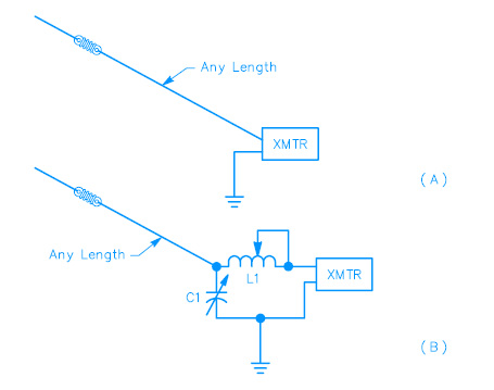
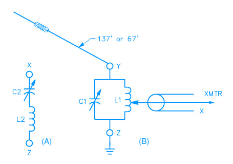
The simplest multiband antenna is a random length of #12 or #14 wire. Power can be fed to the wire on practically any frequency using one or the other of the methods shown in Fig 1. If the wire is made either 67 or 135 feet long, it can also be fed through a tuned circuit, as in Fig 2. It is advantageous to use an SWR bridge or other indicator in the coax line at the point marked “X.”

If you have installed a 28- or 50-MHz rotary beam, in many cases it may be possible to use the beam’s feed line as an antenna on the lower frequencies. Connecting the two wires of the feeder together at the station end will give a random length wire that can be conveniently coupled to the transmitter as in Fig 1. The rotary system at the far end will serve only to end-load the wire and will not have much other effect.

One disadvantage of all such directly fed systems is that part of the antenna is practically within the station, and there is a good chance that you will have some trouble with RF feedback. RF within the station can often be minimized by choosing a length of wire so that the low feed-point impedance at a current loop occurs at or near the transmitter. This means using a wire length of λ/4 (65 feet at 3.6 MHz, 33 feet at 7.1 MHz), or an odd multiple of λ/4 (3⁄4-λ is 195 feet at 3.6 MHz, 100 feet at 7.1 MHz).

Obviously, this can be done for only one band in the case of even harmonically related bands, since the wire length that presents a current loop at the transmitter will present a voltage loop at two (or four) times that frequency.

When you operate with a random-length wire antenna, as in Figs 1 and 2, you should try different types of grounds on the various bands, to see what gives you the best results. In many cases it will be satisfactory to return to the transmitter chassis for the ground, or directly to a convenient metallic water pipe. If neither of these works well (or the metallic water pipe is not available), a length of #12 or #14 wire (approximately λ/4 long) can often be used to good advantage. Connect the wire at the point in the circuit that is shown grounded, and run it out and down the side of the house, or support it a few feet above the ground if the station is on the first floor or in the basement. It should not be connected to actual ground at any point.

Fig 1 - At A, a random-length wire driven directly from the pi-network output of a transmitter. At B, an L network for use in cases where sufficient loading cannot be obtained with the arrangement at A. C1 should have about the same plate spacing as the final tank capacitor in a vacuum-tube type of transmitter; a maximum capacitance of 100 pF is sufficient if L1 is 20 to 25 μH. A suitable coil would consist of 30 turns of #12 wire, 2½ inches diameter, 6 turns per inch. Bare wire should be used so the tap can be placed as required for loading the transmitter.
Fig 2 - If the antenna length is 137 feet, a parallel-tuned coupling circuit can be used on each amateur band from 3.5 through 30 MHz, with the possible exception of the WARC 10-, 18- and 24-MHz bands. C1 should duplicate the final tank tuning capacitor and L1 should have the same dimensions as the final tank inductor on the band being used. If the wire is 67 feet long, series tuning can be used on 3.5 MHz as shown at the left; parallel tuning will be required on 7 MHz and higher frequency bands. C2 and L2 will in general duplicate the final tank tuning capacitor and inductor, the same as with parallel tuning. The L network shown in Fig 1B is also suitable for these antenna lengths.


Source: ARRL Antenna Handbook 2010

HRS Antennas

HRS antennas were invented during the 1920s and 1930s when there was a lot of experimentation with long distance shortwave broadcasting

The Distributed or Branch Feed curtains are considered to be classical HRS type antennas. There are 4 mathematical model types of ITU HRS type HF antennas.

Distributed or Branch Feed curtain arrays are called HR type curtain arrays. The H and R standing for Height and Rows. When they are steerable, they are sometimes called HRS arrays, the S representing "steerable".

An HR 4/3 would be an antenna 4 elements high and 3 elements wide. If it was an HRS 4/3, it would be a steerable array of the same element configuration.

The HRS antenna type was not originally intended for voice and music broadcasting. However, the directional properties of this antenna type were ideal for voice broadcasting—and the design is now pervasive in international broadcasting by the 1950s. As far back as the mid-1930s, Radio Netherlands was using a rotatable HRS antenna for global coverage.

Read the full article on Wikipedia

Thursday, 17 November 2011

Propagation Summary :: 902 - 928 MHz (33cm)

Ionospheric modes of propagation are nearly unknown in the bands above 902 MHz.
Auroral scatter may be just within amateur capabilities at 902 MHz, but signal levels will be well below those at 432 MHz.
Doppler shift and distortion will be considerable, and the signal bandwidth may be quite wide. No other ionospheric propagation modes are likely, although highpowered research radars have received echoes from auroras and meteors as high as 3 GHz.
Almost all extended-distance work in the UHF and microwave bands is accomplished with the aid of tropospheric enhancement. The frequencies above 902 MHz are very sensitive to changes in the weather.
Tropospheric ducting occurs more frequently than in the VHF bands and the potential range is similar. At 1296 MHz, 2000-km (1200-mi) continental paths and 4000-km (2500-mi) paths between California and Hawaii have been spanned many times. Contacts of 1000 km (620 mi) have been made on all bands through 10 GHz in the US and over 1600 km (1000 mi) across the Mediterranean Sea.
Well-equipped 903- and 1296-MHz stations can work reliably up to 300 km (190 mi), but normal working ranges generally shorten with increasing frequency.
Other tropospheric effects become evident in the GHz bands. Evaporation inversions, which form over very warm bodies of water, are usable at 3.3 GHz and higher. It is also possible to complete paths by scattering from rain, snow and hail in the lower GHz bands.
Above 10 GHz, attenuation caused by atmospheric water vapor and oxygen become the most significant limiting factors in long-distance communication.

Propagation Summary :: 430 - 450 MHz (70cm)

The lowest amateur UHF band marks the highest frequency on which ionospheric propagation is commonly observed.
Auroral signals are weaker and more Doppler distorted; the range is usually less than at 144 or 222 MHz.
Meteor scatter is much more difficult than on the lower bands, because bursts are significantly weaker and of much shorter duration.
Although sporadic E and FAI are unknown as high as 432 MHz and probably impossible, TE may be possible.
Well-equipped 432-MHz stations can expect to work over a radius of at least 300 km (190 mi) in the absence of any propagation enhancement.
Tropospheric refraction is more pronounced at 432 MHz and provides the most frequent and useful means of extended-range contacts.
Tropospheric ducting supports contacts of 1500 km (930 mi) and farther over land. The current 432-MHz terrestrial DX record of more than 4000 km (2500 mi) was accomplished by ducting over water.

Wednesday, 16 November 2011

Propagation Summary :: 222 - 225 MHz (135cm)

The 135-cm band shares many characteristics with the 2 meter band.
The normal working range of 222-MHz stations is nearly as far as comparably equipped 144-MHz stations. The 135-cm band is slightly more sensitive to tropospheric effects, but ionospheric modes are more difficult to use.
Auroral and meteorscatter signals are somewhat weaker than at 144 MHz, and sporadic E contacts on 222 MHz are extremely rare.
FAI and TE may also be well within the possibilities of 222 MHz, but reports of these modes on the 135-cm band are uncommon.
Increased activity on 222 MHz will eventually reveal the extent of the propagation modes on the highest of the amateur VHF bands.

Propagation Summary :: 144 - 148 MHz (2m)

Ionospheric effects are significantly reduced at 144 MHz, but they are far from absent.
F layer propagation is unknown except for TE, which is responsible for the current 144-MHz terrestrial DX record of nearly 8000 km (5000 mi).
Sporadic E occurs as high as 144 MHz less than a tenth as often as at 50 MHz, but the usual maximum single-hop distance is the same, about 2300 km (1400 mi). Multiple-hop sporadic E contacts greater than 3000 km (1900 mi) have occurred from time to time across the continental US, as well as across Southern Europe.
Auroral propagation is quite similar to that found at 50 MHz, except that signals are weaker and more Doppler-distorted. Auroral E contacts are rare.
Meteor-scatter contacts are limited primarily to the periods of the great annual meteor showers and require much patience and operating skill. Contacts have been made via FAI on 144 MHz, but its potential has not been fully explored.
Tropospheric effects improve with increasing frequency, and 144 MHz is the lowest VHF band at which weather plays an important propagation role.
Weather-induced enhancements may extend the normal 300- to 600-km (190- to 370-mi) range of wellequipped stations to 800 km (500 mi) and more, especially during the summer and early fall. Tropospheric ducting extends this range to 2000 km (1200 mi) and farther over the continent and at least to 4000 km (2500 mi) over some well-known all-water paths, such as that between California and Hawaii.

Tuesday, 15 November 2011

Propagation Summary :: 50 - 54 MHz (6m)

The lowest amateur VHF band shares many of the characteristics of both lower and higher frequencies. In the absence of any favorable ionospheric propagation conditions, well-equipped 50-MHz stations work regularly over a radius of 300 km (190 mi) via tropospheric scatter, depending on terrain, power, receiver capabilities and antenna.
Weak-signal troposcatter allows the best stations to make 500-km (310-mi) contacts nearly any time. Weather effects may extend the normal range by a few hundred km, especially during the summer months, but true tropospheric ducting is rare.
During the peak of the 11-year sunspot cycle (especially during the winter months), worldwide 50-MHz DX is possible via the F2 layer during daylight hours. F2 backscatter provides an additional propagation mode for contacts as far as 4000 km (2500 mi) when the MUF is just below 50 MHz. TE paths as long as 8000 km (5000 mi) across the magnetic equator are common around the spring and fall equinoxes of peak solar cycle years.
Sporadic E is probably the most common and certainly the most popular form of propagation on the 6 meter band. Single hop E-skip openings may last many hours for contacts from 600 to 2300 km (370 to 1400 mi), primarily during the spring and early summer. Multiple-hop Es provides transcontinental contacts several times a year, and contacts between the US and South America, Europe and Japan via multiple-hop E-skip occur nearly every summer.
Other types of E layer ionospheric propagation make 6 meters an exciting band. Maximum distances of about 2300 km (1400 mi) are typical for all types of E layer modes.
Propagation via FAI often provides additional hours of contacts immediately following sporadic E events.
Auroral propagation often makes its appearance in late afternoon when the geomagnetic field is disturbed. Closely related auroral E propagation may extend the 6 meter range to 4000 km (2500 mi) and sometimes farther across the northern states and Canada, usually after midnight.
Meteor scatter provides brief contacts during the early morning hours, especially during one of the dozen or so prominent annual meteor showers.

Propagation Summary :: 28.0 - 29.7 MHz (10m)

The 10 meter band is well known for extreme variations in characteristics and a variety of propagation modes. During solar maxima, long-distance F2 propagation is so efficient that very low power can produce strong signals halfway around the globe. DX is abundant with modest equipment. Under these conditions, the band is usually open from sunrise to a few hours past sunset.
During periods of moderate solar activity, 10 meters usually opens only to low and trans-equatorial latitudes around noon. During the solar minimum, there may be no F2 propagation at any time during the day or night.
Sporadic E is fairly common on 10 m, especially May through August, although it may appear at any time. Short skip, as sporadic E is sometimes called on the HF bands, has little relation to the solar cycle and occurs regardless of F layer conditions. It provides single-hop communication from 300 to 2300 km (190 to 1400 mi) and multiple-hop opportunities of 4500 km (2800 mi) and farther.
Ten meters is a transitional band in that it also shares some of the propagation modes more characteristic of VHF. Meteor scatter, aurora, auroral E and trans-equatorial propagation provide the means of making contacts out to 2300 km (1400 mi) and farther, but these modes often go unnoticed at 28 MHz.
Techniques similar to those used at VHF can be very effective on 10 meters, as signals are usually stronger and more persistent.

Monday, 14 November 2011

Amateur Radio Designs for Older Operators, by Alexander R. Vegh

Following several weeks of research and gathering Human Factors methodology design principals from various sources, I am pleased to present  a paper entitled "Wide-Ranging design goals and human factors methodologies applied to future Amateur Radio designs for Older Operators" Possible solutions for manufacturers for correcting some of the Human Factors related design shortcomings in future Amateur Radio Designs as it effects Older Operators are identified.

Currently several government, military, aerospace and commercial industries require Human Factors to be incorporated early in the new equipment design phase. I decided to analyze the apparent effects of a general lack of Human Factors design principals when applied to the Amateur Radio industry with special emphasis on how Older Operators are effected.

Why the focus on Older Amateur Radio Operators?

My research revealed some interesting statistics mainly that there presently ~ 3.6 million government licensed Amateur Radio Operators worldwide with the majority of countries reporting the average age of their Amateur Radio Operators being 60+.

Also worth noting, most new Operators wait until they are between 40 and 50 years of age before acquiring their Amateur Radio License.

With Older Amateur Radio Operators now demographically in the majority, Amateur Radio manufacturers must start adopting a New Wide-Ranging Design Philosophy which includes Human Factors Methodologies as applied to the special needs of an Aging Worldwide Amateur Radio Population.

With this goal in mind and offering some solutions for manufacturers to help with implementing this New Wide-Ranging Design Philosophy,  here then is my paper.

Alexander R. Vegh
Industry Canada Licensed Amateur Radio Operator
IC Authorized Call VE2VEH

Click here to download the complete article in MS Word format

Saturday, 12 November 2011

Propagation Summary :: 24.89 - 24.99 MHz (12m)

This band offers propagation that combines the best of the 10 and 15 meter bands.
Although 12 meters is primarily a daytime band during low and moderate sunspot years, it may stay open well after sunset during the solar maximum.
During years of moderate solar activity, 12 meters opens to the low and middle latitudes during the daytime hours, but it seldom remains open after sunset.
Periods of low solar activity seldom cause this band to go completely dead, except at higher latitudes.
Occasional daytime openings, especially in the lower latitudes, are likely over north-south paths.
The main sporadic E season on 24 MHz lasts from late spring through summer and short openings may be observed in mid-winter.

Propagation Summary :: 21.0 - 21.45 MHz (15m)

The 15 meter band has long been considered a prime DX band during solar cycle maxima, but it is sensitive to changing solar activity.
During peak years, 15 meters is reliable for daytime F2 layer DXing and will often stay open well into the night.
During periods of moderate solar activity, 15 meters is basically a daytime-only band, closing shortly after sunset.
During solar minimum periods, 15 meters may not open at all except for infrequent north-south trans-equatorial circuits.
Sporadic E is observed occasionally in early summer and midwinter, although this is not common and the effects are not as pronounced as on the higher frequencies.