Showing posts with label emergency communication. Show all posts

Sunday, 27 May 2012

VA2CYH DMR Repeater is back on the air

Great news for the MotoTRBO enthusiasts in Quebec!

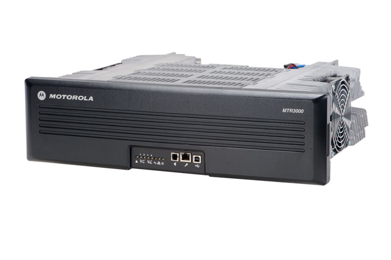
The VA2CYH DMR repeater is operating again, in test mode, on 449.825 MHz (minus) from its location in Covey Hill, Qc.
Powered by the Motorola MTR3000 Digital/Analog repeater, the system runs for now in low power mode (40W) until Alain VA2SPB receives the new duplexer. Once the new duplexer is in place, the repeater will put close to 100W in a 8 bay antenna.
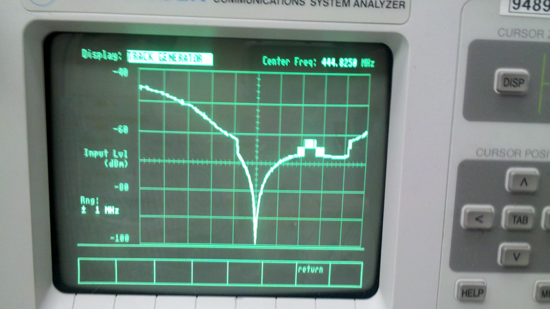
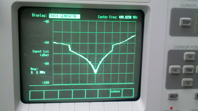
As you can see from the enclosed images, Claude VE2YI did a great job tuning the small Sinclabs duplexer.
Click to enlarge
Click to enlarge

Saturday, 3 March 2012

Curtain Antenna for HF


The curtain antenna is a dipole array, consisting of rows and columns of dipoles. The number of rows can be 1, 2, 3, 4 or 6; the number of columns is usually 2 or 4.

The curtain antenna is a high gain directional antenna, designed for medium and long range communications.

The dipoles are horizontally polarized and a reflector screen is placed behind the dipole array to provide a directive beam.

Curtain antennas are available in two sizes. A low-band array covers the 6, 7, 9 and 11 MHz bands and a high-band array covers the 11, 13, 15, 17 and 21 MHz bands (or 13-26 MHz bands).

The number of dipole columns defines the azimuth beamwidth. For a 2-wide dipole array, the beamwidth is around 50°, for a 4-wide dipole array around 30°. The main beam can be slewed by 15 or 30° so that a maximum coverage of 90° can be achieved.

The number of dipole rows and the height of the lowest element above ground determine the elevation angle and consequently the distance of the service area. A 2-row high array has a typical takeoff angle of 20° and is used for medium range communications, while a 4-row high array has a typical takeoff angle of 10° and is used for long range communications.

The curtain antenna is designed for connection to a 300 ohm balanced open wire feeder.


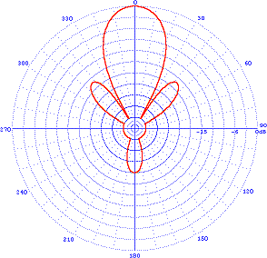
Azimuth pattern
Elevation pattern

Technical Specifications
Azimuth pattern: directional
Frequency ranges: 6-26 MHz, up to 6 adjacent SW bands
Gain: 12.5-22.5 dBi
Input impedance: 300 ohm balanced
Polarization: horizontal
Power ratings: up to 500 kW carrier with 100% modulation

Tree Mounted HF Ground Plane Antenna

A tree-mounted, vertically polarized antenna may not be your first choice. Most engineering references do not recommend it, but such an antenna does not cost much, is inconspicuous, and it works.
The idea was described by Chuck Hutchinson, K8CH, in QST for September 1984.

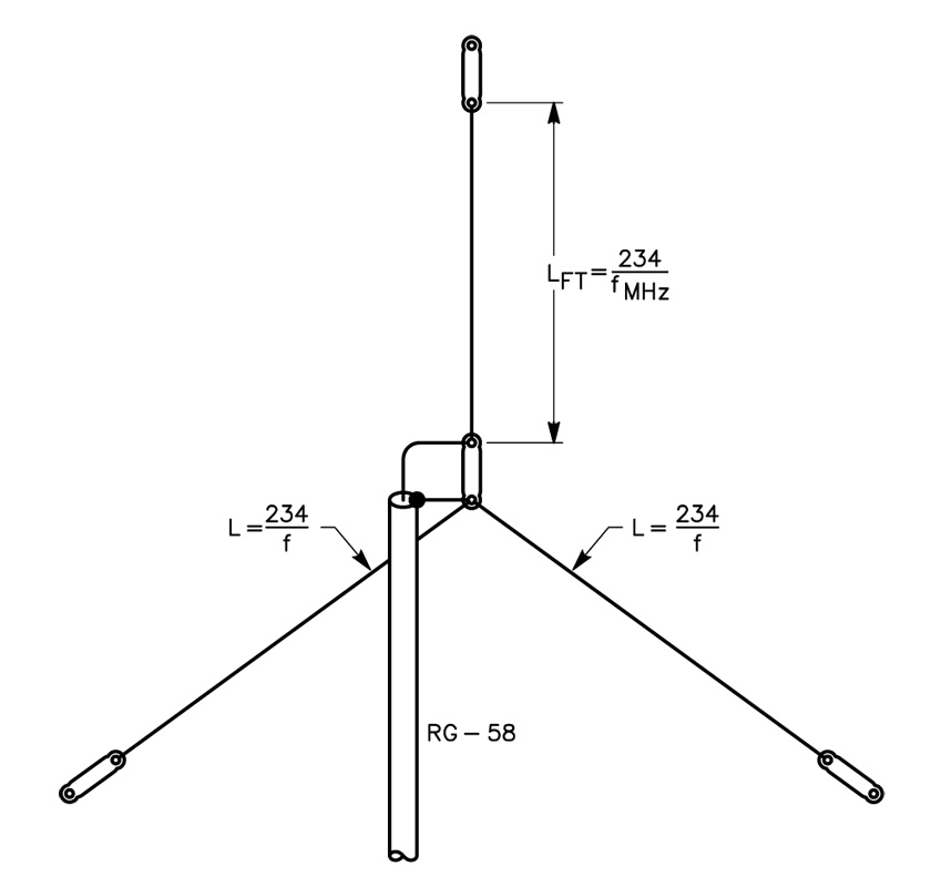
The antenna itself is simple. A piece of RG-58 cable runs to the feed point of the antenna, and is attached to an insulator. Two radial wires are soldered to the coax-line braid at this point. Another piece of wire forms the radiator.

The top of the radiator section is suspended from a tree limb or other convenient support, and in turn supports the rest of the antenna. The dimensions for the antenna are given in the image (click on it to enlarge).

All three wires of the antenna are ¼ wavelength long. This generally limits the usefulness of the antenna for portable operation to 7 MHz and higher bands, as temporary supports higher than 35 or 40 feet are difficult to
come by.

Satisfactory operation might be had on 3.5 MHz with an inverted-L configuration of the radiator, if you can overcome the accompanying difficulty of erecting the antenna at the operating site.

The tree-mounted vertical idea can also be used for fixed station installations to make an invisible antenna.

Saturday, 21 January 2012

Coronal mass ejection heading our way

An active sunspot erupted Thursday, Jan. 19th, producing an M3-class solar flare and a full-halo coronal mass ejection (CME). The Solar and Heliospheric Observatory recorded the cloud expanding almost directly toward Earth.
Analysts at the Goddard Space Weather Lab say strong geomagnetic storms are possible when the cloud arrives this weekend. Their animated forecast track predicts an impact on Jan. 21st at 22:30 UT (+/- 7 hrs).

Thursday, 19 January 2012

Electra Proximity Payload :: SDR ( software-defined radio) by NASA's Jet Propulsion Laboratory

Today, I stumbled upon a little SDR (software-defined radio) package with a big responsibility.

Electra Proximity Payload, is a software-defined radio defined and implemented by the Jet Propulsion Laboratory for use between spacecraft. It is typically used by a lander to communicate with an orbiter that can then communicate with Earth.

Click here to download the complete specifications in PDF format

Sources: Wikipedia and NASA

Sunday, 15 January 2012

Multiband Dipole Antenna

Click on the image to enlarge it
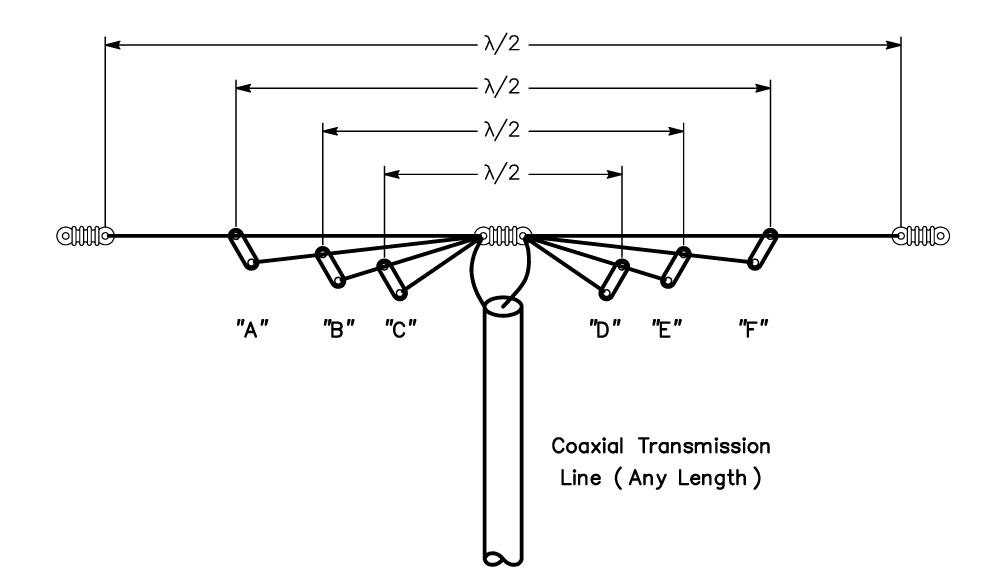
This antenna system consists of a group of center-fed dipoles, all connected in parallel at the point where the transmission line joins them. The dipole elements are stagger-tuned. That is, they are individually cut to be λ/2 at different frequencies.

An extension of the stagger tuning idea is to construct multi-wire dipoles cut for different bands.
In theory, the 4-wire antenna of Fig 14 can be used with a coaxial feeder on five bands. The four wires are prepared as parallel-fed dipoles for 3.5, 7, 14, and 28 MHz. The 7-MHz dipole can be operated on its 3rd harmonic for 21-MHz operation to cover a fifth band. However, in practice it has been found difficult to get a good match to coaxial line on all bands.

The λ/2 resonant length of any one dipole in the presence of the others is not the same as for a dipole by itself due to interaction, and attempts to optimize all four lengths can become a frustrating procedure.
The problem is compounded because the optimum tuning changes in a different antenna environment, so what works for one amateur may not work for another. Even so, many amateurs with limited antenna space are willing to accept the mismatch on some bands just so they can operate on those frequencies using a single coax feed line.

Since this antenna system is balanced, it is desirable to use a balanced transmission line to feed it. The most desirable type of line is 75-ohm transmitting twin-lead. However, either 52-ohm or 75-ohm coaxial line can be used. Coax line introduces some unbalance, but this is tolerable on the lower frequencies. An alternative is to use a balun at the feed point, fed with coaxial cable.

The separation between the dipoles for the various frequencies does not seem to be especially critical. One set of wires can be suspended from the next larger set, using insulating spreaders (of the type used for feeder spreaders) to give a separation of a few inches. Users of this antenna often run some of the dipoles at right angles to each other to help reduce interaction. Some operators use inverted-V mounted dipoles as guy wires for the mast that supports the antenna system.

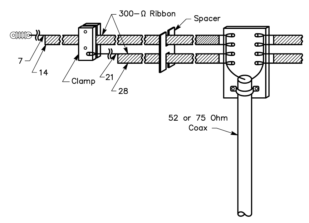
An interesting method of construction used successfully by Louis Richard, ON4UF, is shown below.
The antenna has four dipoles (for 7, 14, 21 and 28 MHz) constructed from 300-ohm ribbon transmission line. A single length of ribbon makes two dipoles. Thus, two lengths, as shown in the sketch, serve to make dipoles for four bands. Ribbon with copper-clad steel conductors (Amphenol type 14-022) should be used because all of the weight, including that of the feed line, must be supported by the uppermost wire. Two pieces of ribbon are first cut to a length suitable for the two halves of the longest dipole.
Then one of the conductors in each piece is cut to proper length for the next band higher in frequency. The excess wire and insulation is stripped away. A second pair of lengths is prepared in the same manner, except that the  lengths are appropriate for the next two higher frequency bands.
Click on the image to enlarge it

A piece of thick polystyrene sheet drilled with holes for anchoring each wire serves as the central insulator. The shorter pair of dipoles is suspended the width of the ribbon below the longer pair by clamps also made of poly sheet. Intermediate spacers are made by sawing slots in pieces of poly sheet so they will fit the ribbon snugly. The multiple-dipole principle can also be applied to vertical antennas. Parallel or fanned λ/4 elements of wire or tubing can be worked against ground or tuned radials from a common feed point.

Source: The ARRL Antenna Handbook

The J-Pole Antenna

Click on the image to enlarge it
The J-Pole is a half-wave antenna that is end-fed at its bottom. Since the radiator is longer than that of a 1/4-wave ground-plane antenna, the vertical lobe is compressed down toward the horizon and it has about 1.5 dB of gain compared to the ground-plane configuration.

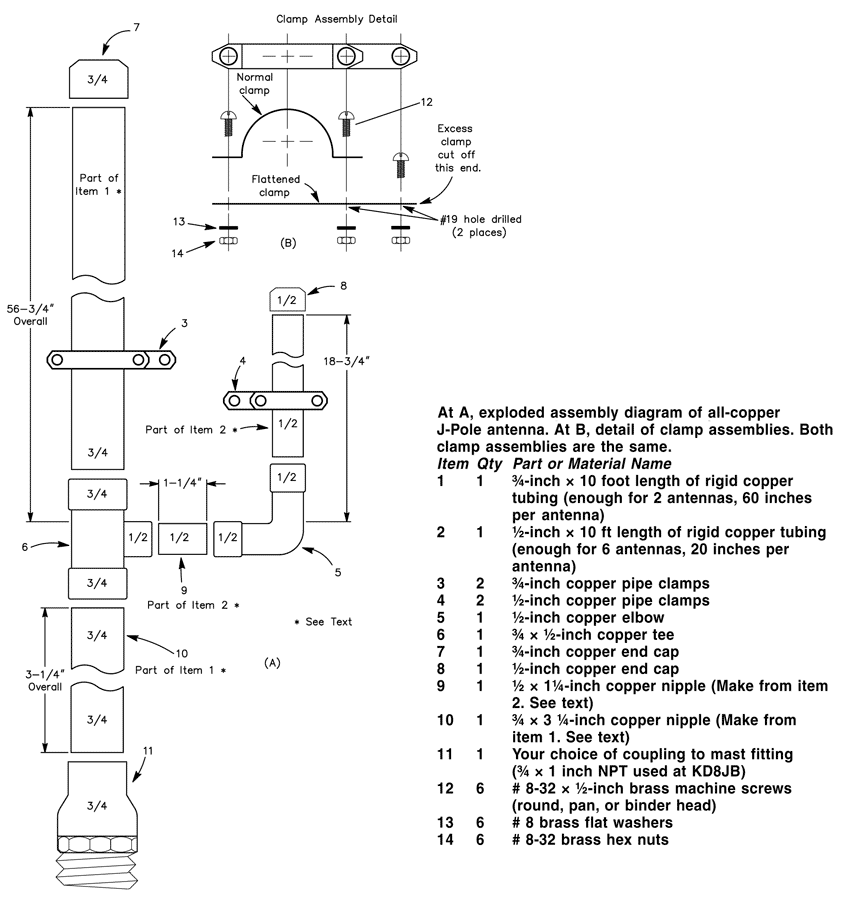
The stub-matching section used to transform the high impedance seen looking into a half-wave to 50 Ω coax is shorted at the bottom, making the antenna look like the letter “J,” and giving the antenna its name.  Rigid copper tubing, fittings and assorted hardware can be used to make a really rugged J-pole antenna for 2 meters. When copper tubing is used, the entire assembly can be soldered together, ensuring electrical integrity, and making the whole antenna weatherproof.

No special hardware or machined parts are used in this antenna, nor are insulating materials needed, since the antenna is always at dc ground. Best of all, even if the parts aren’t on sale, the antenna can be built for less than $15. If you only build one antenna, you’ll have enough tubing left over to make most of a second antenna.

Construction
Copper and brass is used exclusively in this antenna. These metals get along together, so dissimilar metal corrosion is eliminated. Both metals solder well, too.

Cut the copper tubing to the lengths indicated. Item 9 is a 11/4-inch nipple cut from the 20-inch length of 1/2-inch tubing. This leaves 183/4 inches for the 1/4-matching stub. Item 10 is a 31/4-inch long nipple cut from the 60-inch length of 3/4-inch tubing. The 3/4-wave element should measure 563/4-inches long.

Remove burrs from the ends of the tubing after cutting, and clean the mating surfaces with sandpaper, steel wool, or emery cloth. After cleaning, apply a very thin coat of flux to the mating elements and assemble the tubing, elbow, tee, end caps and stubs. Solder the assembled parts with a propane torch and rosin-core solder. Wipe off excess solder with a damp cloth, being careful not to burn yourself.

The copper tubing will hold heat for a long time after you’ve finished soldering. After soldering, set the assembly aside to cool. Flatten one each of the 1/2-inch and 3/4-inch pipe clamps. Drill a hole in the flattened clamp as shown. Assemble the clamps and cut off the excess metal from the flattened clamp using the unmodified clamp as a template. Disassemble the clamps. Assemble the 1/2-inch clamp around the 1/4-wave element and secure with two of the screws, washers, and nuts as shown. Do the same with the 3/4-inch clamp around the 3/4-wave element. Set the clamps initially to a spot about 4 inches above the bottom of the “J” on their respective elements. Tighten the clamps only finger tight, since you’ll need to move them when tuning.

Tuning
The J-Pole can be fed directly from 50-ohm coax through a choke balun (3 turns of the feed coax rolled into a coil about 8 inches in diameter and held together with electrical tape). Before tuning, mount the antenna vertically, about 5 to 10 feet from the ground. A short TV mast on a tripod works well for this purpose.

When tuning VHF antennas, keep in mind that they are sensitive to nearby objects—such as your body. Attach the feed line to the clamps on the antenna, and make sure all the nuts and screws are at least finger tight. It really doesn’t matter to which element (¾-wave element or stub) you attach the coaxial center lead.

Tune the antenna by moving the two feed-point clamps equal distances a small amount each time until the SWR is minimum at the desired frequency. The SWR will be close to 1:1.

Final Assembly
The final assembly of the antenna will determine its long-term survivability. Perform the following steps with care. After adjusting the clamps for minimum SWR, mark the clamp positions with a pencil and then remove the feed line and clamps. Apply a very thin coating of flux to the inside of the clamp and the corresponding surface of the antenna element where the clamp attaches. Install the clamps and tighten the clamp screws.

Solder the feed line clamps where they are attached to the antenna elements. Now, apply a small amount of solder around the screw heads and nuts where they contact the clamps. Don’t get solder on the screw threads! Clean away excess flux with a non-corrosive solvent.

After final assembly and erecting/mounting the antenna in the desired location, attach the feed line and secure with the remaining washer and nut. Weather-seal this joint with RTV.

Source: The ARRL Antenna Handbook

Sunday, 20 November 2011

Marine AIS Search and Rescue Transmitter (SART) Processor

CML Microcircuits has announced the launch of the new cutting-edge Marine AIS Search and Rescue Transmitter (SART) processor, the CMX7045.

An AIS-SART is a self-contained radio transmitter that is deployed by a survival craft or distressed vessel to notify its position for the purpose of rescue. In a rescue situation the device repeatedly transmits its updated position reports using a standard Automatic Identification System (AIS). Position and time synchronisation is derived from an onboard GNSS receiver (e.g. GPS). Every minute the unit transmits multiple position reports to maintain a high probability that at least one of the position reports is sent on the highest point of a wave, guiding rescue services accurately to its location.

The CMX7045 is a highly integrated and flexible baseband processor fulfilling the needs of an AIS-SART and meeting IEC 61097-14 requirements. In addition to providing the core AIS-SART formatted data functionality, the CMX7045 incorporates a number of auxiliary operations that assist in the overall system implementation and therefore reduce component count and cost.


CMX7045 AIS-SART Processor IC:
•    9600 baud GMSK modulator
•    AIS-SART formatted data
•    Very low power sleep modes
•    PA Ramp automation
•    Four DAC outputs
•    Multiplexed two-input ADC
•    System PLL clocks
•    Small 48-pin VQFN/LQFP packages
•    IEC 61097-14 compliant

Retrieved by Claude Everton VE2YI
Source: CML Microcircuits

Amateur radio, a valuable disaster communication resource

Amateur radio technology has historically played an important role in emergency communications during large-scale disasters all around the world.  During Hurricane Katrina, for instance, hundreds of  "ham" radio operators traveled south with their mobile radio equipment to help provide what was often the only method of communications that victims--cut off from telephones, cell and the internet service and even television broadcasts--had with official government information sources.  And during Hurricane Earl in September 2010, amateur enthusiasts manned their highly portable radio equipment to provide critical communications for many of the Red Cross evacuation shelters throughout the Northeast.

That's why it's a so important for emergency managers to reach out to local ham radio operators and groups.  Odds are they'll be more than enthusiastic about volunteering their time, technical know-how and talent to be a part of your emergency communications strategy.

Speaking on behalf of the American Red Cross, Bob Birch, a Red Cross volunteer says, “This isn’t just your grandpa’s quaint little hobby.  The communication networks amateur radio people can stand up and operate instantly have saved many lives in recent months when other systems failed or were overloaded. Amateur radio is a vital part of Red Cross preparedness and response in times of emergency and we stand ready to contribute our skills whenever they are needed.”

Retrieved by Claude Everton VE2YI
Source: Federal Signal Blog