Showing posts with label design. Show all posts

Thursday, 13 December 2012

Re-introduction of the DVRPTR_V1 Boards :: Press Release


Re-introduction of the DVRPTR_V1 Boards as a Low Cost Solution for Building Hotspots, Repeaters and Stand-alone Repeaters

FOR IMMEDIATE RELEASE

Montreal, December 7, 2012

Increased demand for a low-cost solution for building hotspots and repeaters, encouraged the re-introduction of the proven DVRPTR_V1 boards as a viable alternative to the existing offering.

These robust and low-cost boards are a great incentive for many hams to start experimenting with the digital modes.

The "new" DVRPTR_V1 boards will be assembled, individually tested and shipped worldwide from Montreal, Canada. Depending on the demand, the boards are expected to be ready for shipping by the end of February 2013.

" As creator of the original DV-RPTR V1 project (name, hardware and firmware) I'm happy that this project will continue..." said Jan Alte, DO1FJN. "This board is not perfect - I know, but it is a reliable, low-price solution for building hotspots, repeaters and stand-alone repeaters. I will resume my firmware development and I hope to find more dedicated specialists that can help improve the board's open source firmware."

Bruce Given, VE2GZI, hardware engineer with over 20 years of experience in the electronic components business, will coordinate the production and logistics efforts of this project.

"My top priority is to promote this great product in the amateur community and to offer it bundled with timely delivery, excellent service and technical support" said Bruce Given, VE2GZI.

Contact information:
Bruce Given, VE2GZI, bruce.given@gmail.com
http://groups.yahoo.com/group/DVRPTR_V1/

Tuesday, 3 July 2012

Low power computing platforms for amateur radio :: by Bruce Given VE2GZI

There has been a explosion of cheap and powerful computing platforms appearing in the hobbyist/maker market in the last year.

While these boards can be used in a myriad of digital applications for amateur radio, the purpose of this article is take a quick look at what is out there, to plant some seeds and get the creativeness flowing...

All of these boards run a version of the Linux operations system which is a free Unix like operating system it has a number of advantages over the Microsoft based offerings.

  • It’s free !
  • Posix compliance (reacts to real time events better than windows)
  • Large community support
  • Open source ( Code is open to scrutiny and can be modified for your needs )
  • Complete software development suites in most languages (C++, Java, .Net etc… )
  • Can be configured for a nice graphical interface or Command line interface

Let’s take a look at what’s out there!

I will be ignoring the both the Panda board and the Beagle boards as these are targeted to more of a development environment or are more expensive.

Let`s start with the board that’s creating a lot of buzz

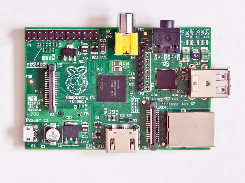
Raspberry Pi [www.raspberrypi.org]
Price: $35.00
Based on the Broadcomm BCM2835 System on a chip.

•    ARM 11 running at 700 MHz processor,
•    Video GPU
•    256 Megabytes of Ram ( Can’t be upgraded)
•    2 USB 2.0 ports
•    HDMI and Composite Video outputs
•    10/100 Ethernet RJ-45 Jack
•    SD Card socket
•    8 × GPIO, UART, I²C bus, SPI bus with two chip selects, +3.3 V, +5 V, ground
•    Audio output from HDMI as well from a standard 3.5mm jack

All in a board 85.60mm x 53.98mm x 17mm.

Current operating systems for this are Debian GNU/Linux, Fedora, Arch Linux ARM, all of these are available on the web so all you have to download them copy them to the SD card and boot the Pi from the SD and you are up and running with a Graphical Linux Operating system.

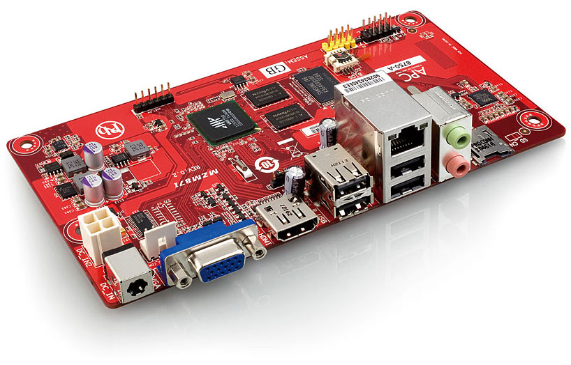
APC [www.apc.io]
Price:  $49.00
Based on the Via’s Wondermedia  WM8750 System On a Chip

•    ARM 11 running at 800 MHz processor,
•    Video GPU
•    512 Megabytes of Ram ( Can’t be upgraded)
•    4 USB 2.0 ports
•    HDMI and VGA Video outputs
•    10/100 Ethernet RJ-45 Jack
•    MicroSD Card socket
•    Audio output/Input from a standard 3.5mm jack

All this in 170 x 85mm package, this is the NEO-ITX standard which is compatible with Mini-ITX and MicroATX  (this means it will fit in a MicroATX/Mini-ITX PC case).

Currently the only operating system for this is Android 2.3 which ships with it (pretty sure that within a couple of months that there will be a couple of flavors of Linux available for it)

OK, so we have the platforms what are we going to do with them? Well let’s see what some of our fellow hams have started to do …

John Hays of NW Digital radio has successfully downloaded and run Jonathan Naylor’s (G4KLX)         GMSK Repeater and IrcDDB Gateway software on the Raspberry Pi  and there is a D-Star repeater LD1XI in Norway that is now running on the Raspberry Pi connected to the DVRPTR.

The code was even complied on the Raspberry Pi; the OS is Debian "Squeeze" beta. IrcDDBgateway  and DVRPTR repeater run at 10-11% CPU each when active.

Although the APC, which has a little more computing power maybe a better choice, having a D-Star hotspot for the price of the GMSK board and a Raspberry Pi, that’s pretty cool! You are no longer using a PC as the controller.

Expanding on the D-Star hotspot: how about a portable, solar powered, D-Star hotspot based on a APC or Raspberry Pi, with a wireless USB adapter, a GMSK Modem board? Paired with a AMBE codec board it could enable a standard radio to become a D-star radio on any frequency (220mhz, HF,  whatever you'd like...)

Another application for these low power computing platforms could be a controller for a SDR ( Software Defined  Radio). But,  that is a topic that we will get on to on a future article.

Conclusion

By combining digital radio with small form factor, low cost computing platforms and open source free software we have a great recipe for experimentation and a way of getting younger internet savvy  people back into the hobby.

I hope that I have given you a quick look at some of the exciting things that are coming our way and if I can be of any help or if you just want to ask questions you can find me at bruce.given@gmail.com

73, Bruce VE2GZI

Sunday, 10 June 2012

My Modular Approach To HF Digital Interfacing :: by Steve Perron VA2PSL


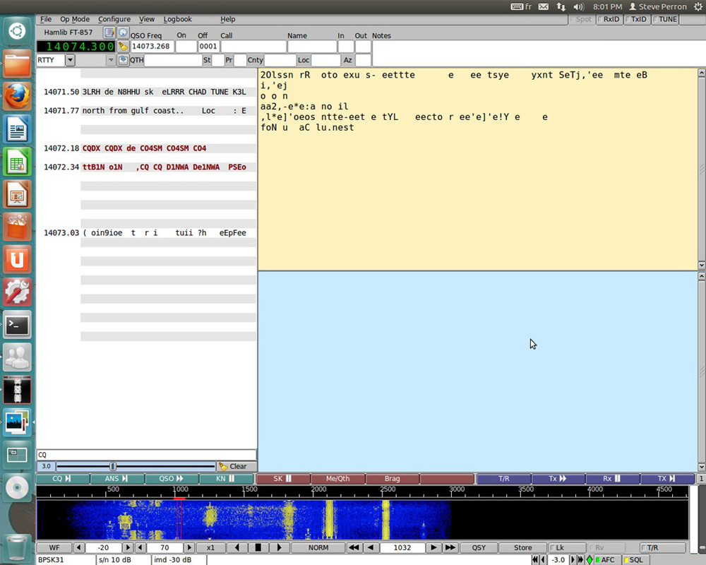
While I do have another interface I built a few years back on a PC board with isolation transformers, RS232 to PTT, VOX PTT and even a sound card to Morse keying interface, I prefer to use a more modular approach to interfacing HF transceivers to a sound card to use the various digital modes. Because getting on HF digital has been as simple as hooking up your transceiver to the sound card of your computer, there's been a wide range of new applications and modes available to experiment with over the past decade. I started playing around with PSK31 when it came out in the late 90s, and my first interface was a simple cable from my sound card to the back of my Icom 735, no audio isolation. I also used an RS232 to PTT that was made with a resistor and the perennial 2N2222a. It worked great, so keep this in mind.
Now, my current little HF rig, the FT-857 is not as simple to interface as some of the newer rigs like the Icom 7200 or the Kenwood TS590 which have built-in USB sound card and radio control, but it does provide a lot more functionality than my old 735. For starters, the radio has settings for audio gain when running digital, aka the back input/output on the rig. There's also a digital VOX and PTT through the CAT interface.

Part 1: The USB Serial Cable

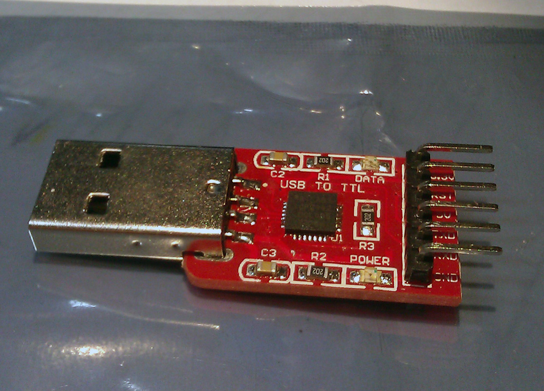
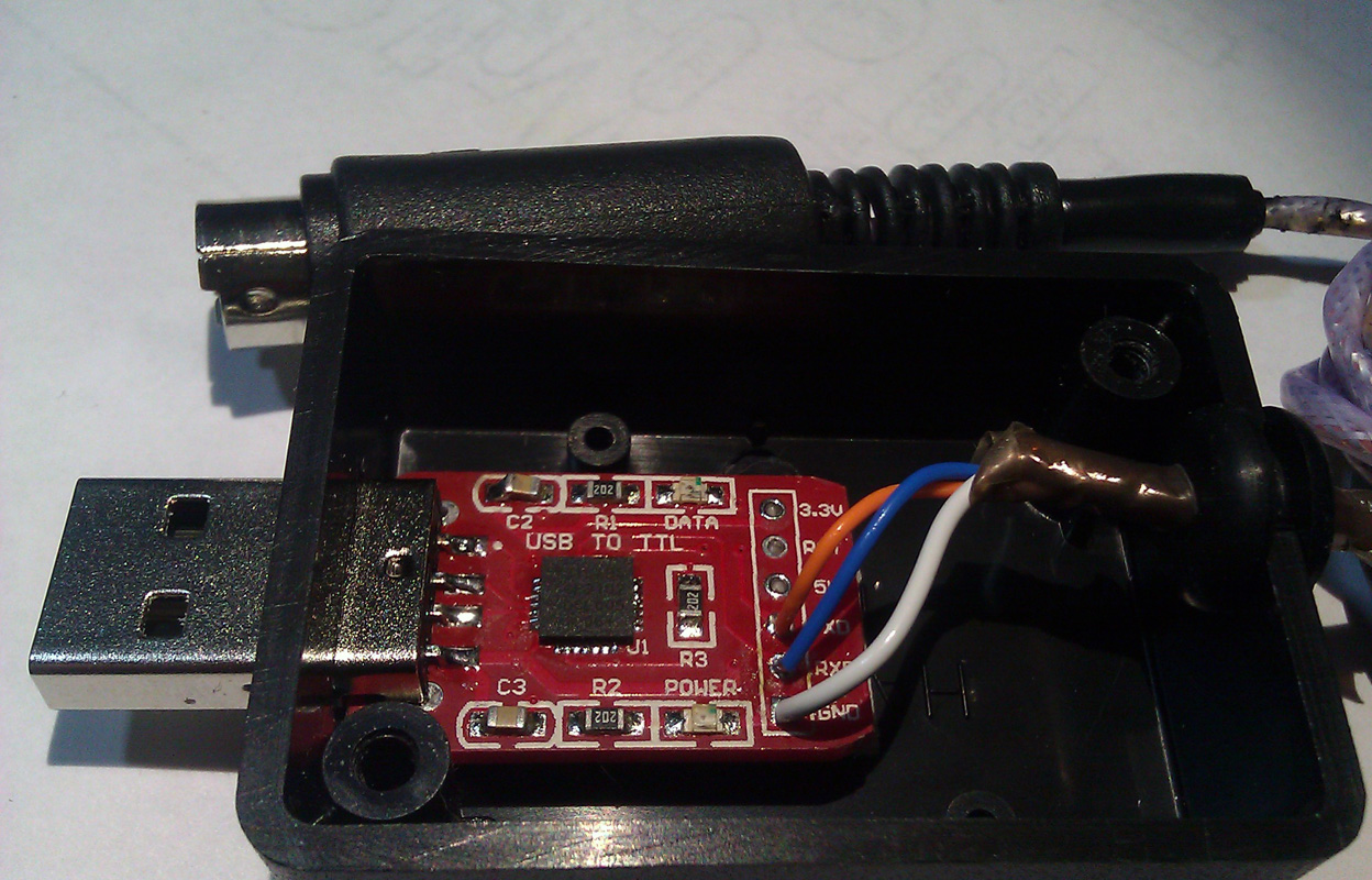
Almost all transceivers made since the mid 80s have some form of serial port interface which provide for the control of the mode, frequency, PTT and on the newer rigs, a lot more. If you've played with Ham Radio Deluxe, you actually get a pretty complete panel to control your radio. Most plans you'll find online or in the magazines are simple RS232 voltage converters (+12V to -12V) to TTL (0V to +5V). You can order USB cables from various sources, but they tend to use the Prolific PL2303 chip which has been cloned by Chinese chip manufacturers. Prolific has added an anti-clone feature in their drivers which is why all these USB programming cables from China do not work with the latest drivers. I had a CAT (Yaesu's name for this interface) USB cable with the PL2303 clone, and it simply died on me. My new interface uses the CP2102 from Silicon labs. The drivers actually work, and you can pick up the ready-made modules on eBay for less than 3$. As I said earlier, quite a few software support the PTT functionality directly through this interface, including my favorite software, FLDIGI. FLDIGI is available on most operating systems, including Linux. So when running FLDIGI, I get both the control of the mode/frequency and the PTT using my simple USB to CAT interface. See the pictures below. All that is required on the Yaesu and Kenwood is for the RX/TX and GND to be connected to the connector on the back of the transceiver. If you're using an Icom transceiver, the RX and TX would be tied together, since the interface is half-duplex. My module did not follow the convention of RX->TX, TX->RX, but rather RX->RX and TX->TX, so please be aware. If it's not working for you, simply swap the wires around. In windows, the interface will be assigned a Com port. Under Linux, it will be /dev/ttyUSB0, when the 0 could be a different number if like me you have more than one USB-Serial cable attached.

Part 2: The Sound card Interface


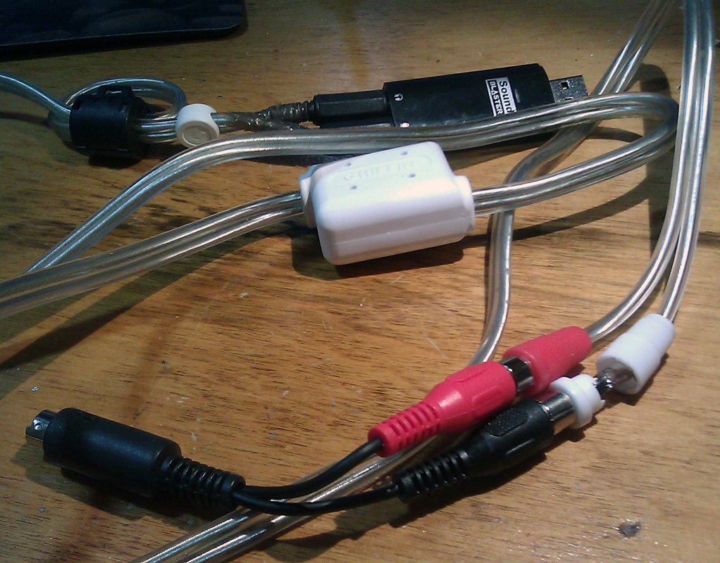
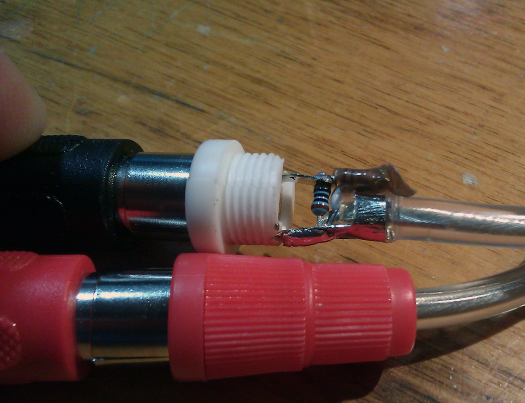
My audio interface is even simpler. I simply used half of an audio cable with female RCA jacks soldered to a mini-din8 on the ground, Audio in and Audio Out pins. I'm later going to add another RCA jack for the PTT line. My other cable is an eBay-special Griffin stereo isolation cable. While this cable is not available anymore, any similar cable/interface could be used. I installed 3.5mm stereo plugs on one end, and I replaced the male RCA on the other end so that I could make a simple voltage divider to reduce the audio amplitude of the signal so it would be more compatible with most transceivers out there. It's not required on the FT857 thanks to the programmable audio gain, but I want my cable to be compatible with most rigs. The voltage divider is simply two resistors, 10k and 1k, soldered inside the RCA jack going to the audio in of the transceiver. You can see that I'm also using a USB sound card. This is mostly to avoid transmitting operating system sounds and some laptops lack any form of audio input.


Part 3: The Optional RS232 PTT Interface

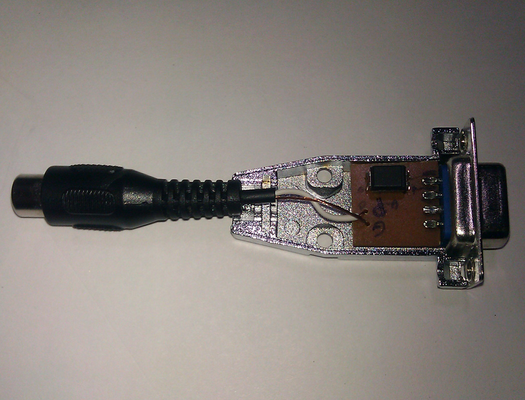
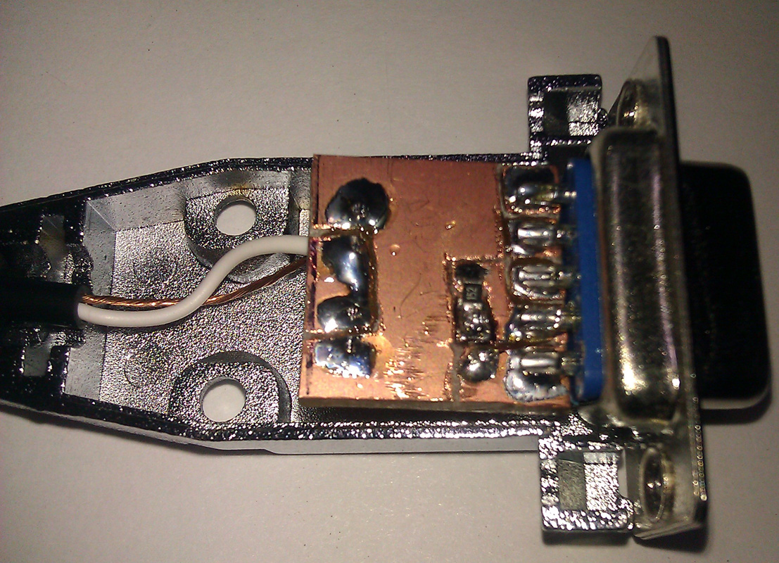
This interface is simply an opto-isolator inside a DB9 housing. It can be used with any serial port, including most USB-Serial cables. The CP2102 module I discussed earlier lacks the required RTS or DTR signals. To keep the little PCB as simple as possible, I only use the DTR. The PCB was done freehand using a Dremel tool. You can find the schematic of the interface online or even in the ARRL handbook. This interface would be required if the software does not support CAT PTT, VOX is not available or undesirable. An example of this would be when running the UZ7HO sound card packet modem. There are numerous amateurs using APRS on HF with this modem. Alternatively, it could also be used as a software Morse keyer. N1MM and other logging software support this as well as the CW-daemon in Linux.


Part 4: Digital Modes Software and Random Ramblings

There are a few software I find more interesting. FLDIGI is the Swiss army-knife of digital modes. I'm only aware of one software that supports more different modes, MultiPSK, but I find it not user-friendly and it does not run on Linux. PSK Mail is a software than runs of top of FLDIGI and provides ARQ email throughout the world (Think Amtor, Pactor). Winmor is a modem that can be used with RMS Express to provide access to the Winlink 2000 system without an expensive SCS-PTC Pactor modem. While I would not rely on Winmor to do mission-critical emails, it can be useful to check your emails if you're in an area that does not have any other forms of coverage. Winmor is only available on Windows.
I don't recommend using the microphone jack unless your rig only has this input. The microphone jack has much more gain than the digital port at the back of your radio and this can lead to over-modulation. Most commercially made interfaces simply regroup all these functionalities in a pretty box. The wildly popular Signalink interface from Tigertronics is a USB soundcard with audio isolation and a VOX setup. The VOX would be redundant on my transceiver, and I prefer not to use VOX, as it tends to mangle most ARQ modes, like HF packet. The first few milliseconds of the transmission would be missing because VOX always has latency.

Sunday, 15 January 2012

Multiband Dipole Antenna

Click on the image to enlarge it
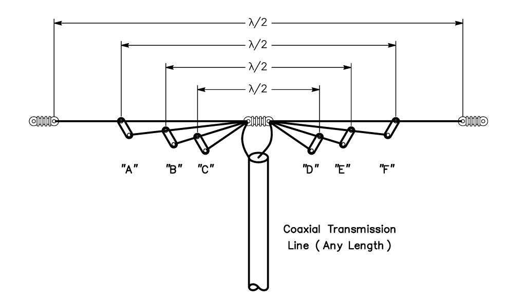
This antenna system consists of a group of center-fed dipoles, all connected in parallel at the point where the transmission line joins them. The dipole elements are stagger-tuned. That is, they are individually cut to be λ/2 at different frequencies.

An extension of the stagger tuning idea is to construct multi-wire dipoles cut for different bands.
In theory, the 4-wire antenna of Fig 14 can be used with a coaxial feeder on five bands. The four wires are prepared as parallel-fed dipoles for 3.5, 7, 14, and 28 MHz. The 7-MHz dipole can be operated on its 3rd harmonic for 21-MHz operation to cover a fifth band. However, in practice it has been found difficult to get a good match to coaxial line on all bands.

The λ/2 resonant length of any one dipole in the presence of the others is not the same as for a dipole by itself due to interaction, and attempts to optimize all four lengths can become a frustrating procedure.
The problem is compounded because the optimum tuning changes in a different antenna environment, so what works for one amateur may not work for another. Even so, many amateurs with limited antenna space are willing to accept the mismatch on some bands just so they can operate on those frequencies using a single coax feed line.

Since this antenna system is balanced, it is desirable to use a balanced transmission line to feed it. The most desirable type of line is 75-ohm transmitting twin-lead. However, either 52-ohm or 75-ohm coaxial line can be used. Coax line introduces some unbalance, but this is tolerable on the lower frequencies. An alternative is to use a balun at the feed point, fed with coaxial cable.

The separation between the dipoles for the various frequencies does not seem to be especially critical. One set of wires can be suspended from the next larger set, using insulating spreaders (of the type used for feeder spreaders) to give a separation of a few inches. Users of this antenna often run some of the dipoles at right angles to each other to help reduce interaction. Some operators use inverted-V mounted dipoles as guy wires for the mast that supports the antenna system.

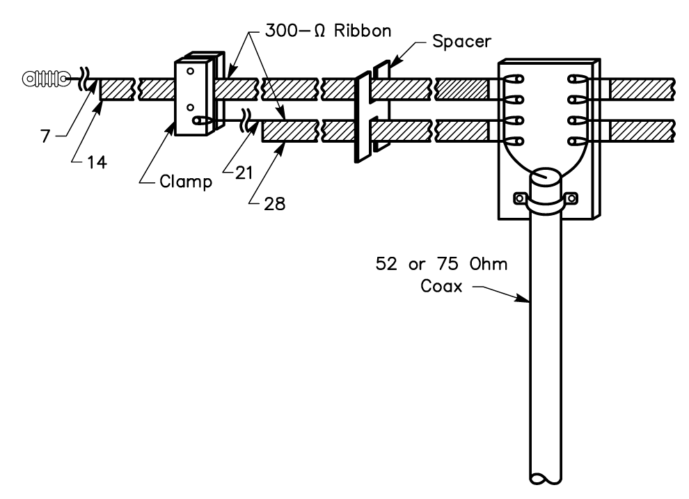
An interesting method of construction used successfully by Louis Richard, ON4UF, is shown below.
The antenna has four dipoles (for 7, 14, 21 and 28 MHz) constructed from 300-ohm ribbon transmission line. A single length of ribbon makes two dipoles. Thus, two lengths, as shown in the sketch, serve to make dipoles for four bands. Ribbon with copper-clad steel conductors (Amphenol type 14-022) should be used because all of the weight, including that of the feed line, must be supported by the uppermost wire. Two pieces of ribbon are first cut to a length suitable for the two halves of the longest dipole.
Then one of the conductors in each piece is cut to proper length for the next band higher in frequency. The excess wire and insulation is stripped away. A second pair of lengths is prepared in the same manner, except that the  lengths are appropriate for the next two higher frequency bands.
Click on the image to enlarge it

A piece of thick polystyrene sheet drilled with holes for anchoring each wire serves as the central insulator. The shorter pair of dipoles is suspended the width of the ribbon below the longer pair by clamps also made of poly sheet. Intermediate spacers are made by sawing slots in pieces of poly sheet so they will fit the ribbon snugly. The multiple-dipole principle can also be applied to vertical antennas. Parallel or fanned λ/4 elements of wire or tubing can be worked against ground or tuned radials from a common feed point.

Source: The ARRL Antenna Handbook

The J-Pole Antenna

Click on the image to enlarge it
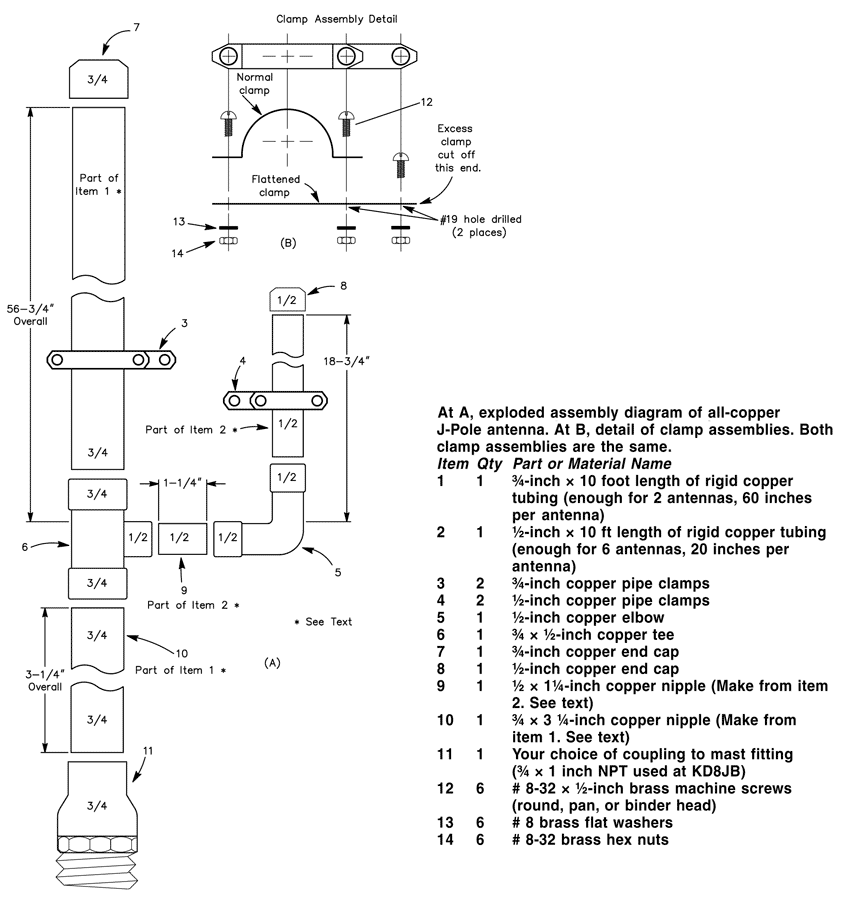
The J-Pole is a half-wave antenna that is end-fed at its bottom. Since the radiator is longer than that of a 1/4-wave ground-plane antenna, the vertical lobe is compressed down toward the horizon and it has about 1.5 dB of gain compared to the ground-plane configuration.

The stub-matching section used to transform the high impedance seen looking into a half-wave to 50 Ω coax is shorted at the bottom, making the antenna look like the letter “J,” and giving the antenna its name.  Rigid copper tubing, fittings and assorted hardware can be used to make a really rugged J-pole antenna for 2 meters. When copper tubing is used, the entire assembly can be soldered together, ensuring electrical integrity, and making the whole antenna weatherproof.

No special hardware or machined parts are used in this antenna, nor are insulating materials needed, since the antenna is always at dc ground. Best of all, even if the parts aren’t on sale, the antenna can be built for less than $15. If you only build one antenna, you’ll have enough tubing left over to make most of a second antenna.

Construction
Copper and brass is used exclusively in this antenna. These metals get along together, so dissimilar metal corrosion is eliminated. Both metals solder well, too.

Cut the copper tubing to the lengths indicated. Item 9 is a 11/4-inch nipple cut from the 20-inch length of 1/2-inch tubing. This leaves 183/4 inches for the 1/4-matching stub. Item 10 is a 31/4-inch long nipple cut from the 60-inch length of 3/4-inch tubing. The 3/4-wave element should measure 563/4-inches long.

Remove burrs from the ends of the tubing after cutting, and clean the mating surfaces with sandpaper, steel wool, or emery cloth. After cleaning, apply a very thin coat of flux to the mating elements and assemble the tubing, elbow, tee, end caps and stubs. Solder the assembled parts with a propane torch and rosin-core solder. Wipe off excess solder with a damp cloth, being careful not to burn yourself.

The copper tubing will hold heat for a long time after you’ve finished soldering. After soldering, set the assembly aside to cool. Flatten one each of the 1/2-inch and 3/4-inch pipe clamps. Drill a hole in the flattened clamp as shown. Assemble the clamps and cut off the excess metal from the flattened clamp using the unmodified clamp as a template. Disassemble the clamps. Assemble the 1/2-inch clamp around the 1/4-wave element and secure with two of the screws, washers, and nuts as shown. Do the same with the 3/4-inch clamp around the 3/4-wave element. Set the clamps initially to a spot about 4 inches above the bottom of the “J” on their respective elements. Tighten the clamps only finger tight, since you’ll need to move them when tuning.

Tuning
The J-Pole can be fed directly from 50-ohm coax through a choke balun (3 turns of the feed coax rolled into a coil about 8 inches in diameter and held together with electrical tape). Before tuning, mount the antenna vertically, about 5 to 10 feet from the ground. A short TV mast on a tripod works well for this purpose.

When tuning VHF antennas, keep in mind that they are sensitive to nearby objects—such as your body. Attach the feed line to the clamps on the antenna, and make sure all the nuts and screws are at least finger tight. It really doesn’t matter to which element (¾-wave element or stub) you attach the coaxial center lead.

Tune the antenna by moving the two feed-point clamps equal distances a small amount each time until the SWR is minimum at the desired frequency. The SWR will be close to 1:1.

Final Assembly
The final assembly of the antenna will determine its long-term survivability. Perform the following steps with care. After adjusting the clamps for minimum SWR, mark the clamp positions with a pencil and then remove the feed line and clamps. Apply a very thin coating of flux to the inside of the clamp and the corresponding surface of the antenna element where the clamp attaches. Install the clamps and tighten the clamp screws.

Solder the feed line clamps where they are attached to the antenna elements. Now, apply a small amount of solder around the screw heads and nuts where they contact the clamps. Don’t get solder on the screw threads! Clean away excess flux with a non-corrosive solvent.

After final assembly and erecting/mounting the antenna in the desired location, attach the feed line and secure with the remaining washer and nut. Weather-seal this joint with RTV.

Source: The ARRL Antenna Handbook

Monday, 14 November 2011

Amateur Radio Designs for Older Operators, by Alexander R. Vegh

Following several weeks of research and gathering Human Factors methodology design principals from various sources, I am pleased to present  a paper entitled "Wide-Ranging design goals and human factors methodologies applied to future Amateur Radio designs for Older Operators" Possible solutions for manufacturers for correcting some of the Human Factors related design shortcomings in future Amateur Radio Designs as it effects Older Operators are identified.

Currently several government, military, aerospace and commercial industries require Human Factors to be incorporated early in the new equipment design phase. I decided to analyze the apparent effects of a general lack of Human Factors design principals when applied to the Amateur Radio industry with special emphasis on how Older Operators are effected.

Why the focus on Older Amateur Radio Operators?

My research revealed some interesting statistics mainly that there presently ~ 3.6 million government licensed Amateur Radio Operators worldwide with the majority of countries reporting the average age of their Amateur Radio Operators being 60+.

Also worth noting, most new Operators wait until they are between 40 and 50 years of age before acquiring their Amateur Radio License.

With Older Amateur Radio Operators now demographically in the majority, Amateur Radio manufacturers must start adopting a New Wide-Ranging Design Philosophy which includes Human Factors Methodologies as applied to the special needs of an Aging Worldwide Amateur Radio Population.

With this goal in mind and offering some solutions for manufacturers to help with implementing this New Wide-Ranging Design Philosophy,  here then is my paper.

Alexander R. Vegh
Industry Canada Licensed Amateur Radio Operator
IC Authorized Call VE2VEH

Click here to download the complete article in MS Word format