Showing posts with label D-STAR. Show all posts

Thursday, 13 December 2012

Re-introduction of the DVRPTR_V1 Boards :: Press Release


Re-introduction of the DVRPTR_V1 Boards as a Low Cost Solution for Building Hotspots, Repeaters and Stand-alone Repeaters

FOR IMMEDIATE RELEASE

Montreal, December 7, 2012

Increased demand for a low-cost solution for building hotspots and repeaters, encouraged the re-introduction of the proven DVRPTR_V1 boards as a viable alternative to the existing offering.

These robust and low-cost boards are a great incentive for many hams to start experimenting with the digital modes.

The "new" DVRPTR_V1 boards will be assembled, individually tested and shipped worldwide from Montreal, Canada. Depending on the demand, the boards are expected to be ready for shipping by the end of February 2013.

" As creator of the original DV-RPTR V1 project (name, hardware and firmware) I'm happy that this project will continue..." said Jan Alte, DO1FJN. "This board is not perfect - I know, but it is a reliable, low-price solution for building hotspots, repeaters and stand-alone repeaters. I will resume my firmware development and I hope to find more dedicated specialists that can help improve the board's open source firmware."

Bruce Given, VE2GZI, hardware engineer with over 20 years of experience in the electronic components business, will coordinate the production and logistics efforts of this project.

"My top priority is to promote this great product in the amateur community and to offer it bundled with timely delivery, excellent service and technical support" said Bruce Given, VE2GZI.

Contact information:
Bruce Given, VE2GZI, bruce.given@gmail.com
http://groups.yahoo.com/group/DVRPTR_V1/

Tuesday, 3 July 2012

Low power computing platforms for amateur radio :: by Bruce Given VE2GZI

There has been a explosion of cheap and powerful computing platforms appearing in the hobbyist/maker market in the last year.

While these boards can be used in a myriad of digital applications for amateur radio, the purpose of this article is take a quick look at what is out there, to plant some seeds and get the creativeness flowing...

All of these boards run a version of the Linux operations system which is a free Unix like operating system it has a number of advantages over the Microsoft based offerings.

  • It’s free !
  • Posix compliance (reacts to real time events better than windows)
  • Large community support
  • Open source ( Code is open to scrutiny and can be modified for your needs )
  • Complete software development suites in most languages (C++, Java, .Net etc… )
  • Can be configured for a nice graphical interface or Command line interface

Let’s take a look at what’s out there!

I will be ignoring the both the Panda board and the Beagle boards as these are targeted to more of a development environment or are more expensive.

Let`s start with the board that’s creating a lot of buzz

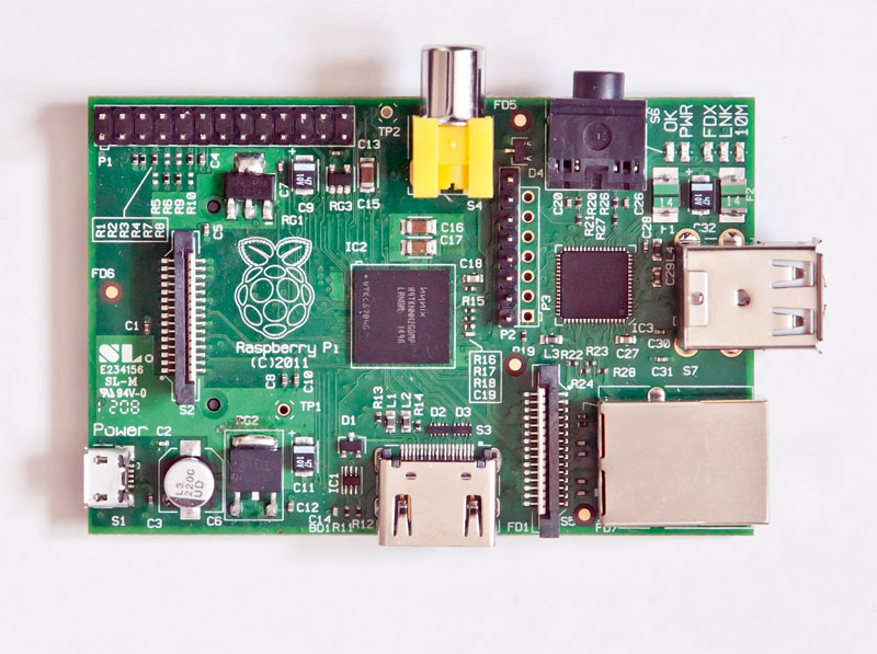
Raspberry Pi [www.raspberrypi.org]
Price: $35.00
Based on the Broadcomm BCM2835 System on a chip.

•    ARM 11 running at 700 MHz processor,
•    Video GPU
•    256 Megabytes of Ram ( Can’t be upgraded)
•    2 USB 2.0 ports
•    HDMI and Composite Video outputs
•    10/100 Ethernet RJ-45 Jack
•    SD Card socket
•    8 × GPIO, UART, I²C bus, SPI bus with two chip selects, +3.3 V, +5 V, ground
•    Audio output from HDMI as well from a standard 3.5mm jack

All in a board 85.60mm x 53.98mm x 17mm.

Current operating systems for this are Debian GNU/Linux, Fedora, Arch Linux ARM, all of these are available on the web so all you have to download them copy them to the SD card and boot the Pi from the SD and you are up and running with a Graphical Linux Operating system.

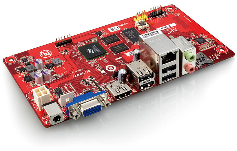
APC [www.apc.io]
Price:  $49.00
Based on the Via’s Wondermedia  WM8750 System On a Chip

•    ARM 11 running at 800 MHz processor,
•    Video GPU
•    512 Megabytes of Ram ( Can’t be upgraded)
•    4 USB 2.0 ports
•    HDMI and VGA Video outputs
•    10/100 Ethernet RJ-45 Jack
•    MicroSD Card socket
•    Audio output/Input from a standard 3.5mm jack

All this in 170 x 85mm package, this is the NEO-ITX standard which is compatible with Mini-ITX and MicroATX  (this means it will fit in a MicroATX/Mini-ITX PC case).

Currently the only operating system for this is Android 2.3 which ships with it (pretty sure that within a couple of months that there will be a couple of flavors of Linux available for it)

OK, so we have the platforms what are we going to do with them? Well let’s see what some of our fellow hams have started to do …

John Hays of NW Digital radio has successfully downloaded and run Jonathan Naylor’s (G4KLX)         GMSK Repeater and IrcDDB Gateway software on the Raspberry Pi  and there is a D-Star repeater LD1XI in Norway that is now running on the Raspberry Pi connected to the DVRPTR.

The code was even complied on the Raspberry Pi; the OS is Debian "Squeeze" beta. IrcDDBgateway  and DVRPTR repeater run at 10-11% CPU each when active.

Although the APC, which has a little more computing power maybe a better choice, having a D-Star hotspot for the price of the GMSK board and a Raspberry Pi, that’s pretty cool! You are no longer using a PC as the controller.

Expanding on the D-Star hotspot: how about a portable, solar powered, D-Star hotspot based on a APC or Raspberry Pi, with a wireless USB adapter, a GMSK Modem board? Paired with a AMBE codec board it could enable a standard radio to become a D-star radio on any frequency (220mhz, HF,  whatever you'd like...)

Another application for these low power computing platforms could be a controller for a SDR ( Software Defined  Radio). But,  that is a topic that we will get on to on a future article.

Conclusion

By combining digital radio with small form factor, low cost computing platforms and open source free software we have a great recipe for experimentation and a way of getting younger internet savvy  people back into the hobby.

I hope that I have given you a quick look at some of the exciting things that are coming our way and if I can be of any help or if you just want to ask questions you can find me at bruce.given@gmail.com

73, Bruce VE2GZI

Sunday, 29 January 2012

REPEATER SYSTEMS : Cavity resonators and duplexers

Cavity Resonators

Receiver desensing can be reduced by separating the transmitter and receiver antennas. But the amount of transmitted energy that reaches the receiver input must often be decreased even farther. Other nearby transmitters can cause desensing as well. A cavity resonator (cavity filter) can be helpful in solving these problems.

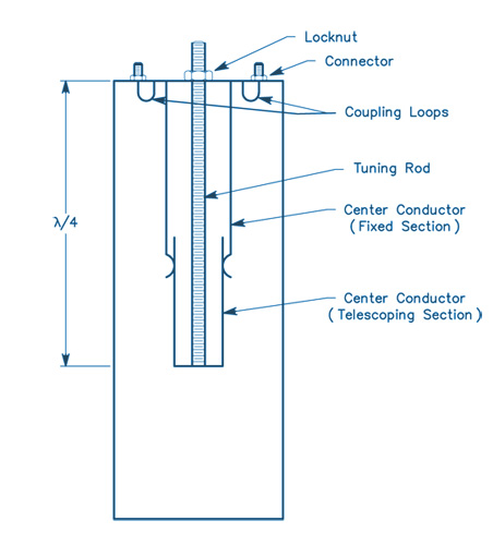
When properly designed and constructed, this type of resonator has very high Q. A cavity resonator placed in series with a transmission line acts as a band-pass filter. For a resonator to operate in series, it must have input and output coupling loops (or probes). A cavity resonator can also be connected across (in parallel with) a transmission line. The cavity then acts as a band-reject (notch) filter, greatly attenuating energy at the frequency to which it is tuned.

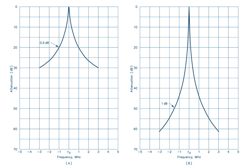
Only one coupling loop or probe is required for this method of filtering. This type of cavity could be used in the receiver line to "notch" the transmitter signal. Several cavities can be connected in series or parallel to increase the attenuation in a given configuration. The diagram below show the attenuation of a single cavity (A) and a pair of cavities (B).

The only situation in which cavity filters would not help is the case where the off-frequency noise of the transmitter was right on the receiver frequency. With cavity resonators, an important point to remember is that addition of a cavity across a transmission line may change the impedance of the system. This change can be compensated by adding tuning stubs along the transmission line.


Duplexers

Most amateur repeaters in the 144, 220 and 440 MHz bands use duplexers to obtain the necessary transmitter to receiver isolation. Duplexers have been commonly used in commercial repeaters for many years.

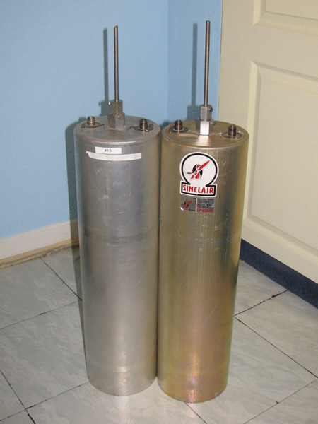
The duplexer consists of two high-Q filters. One filter is used in the feed line from the transmitter to the antenna, and another between the antenna and the receiver. These filters must have low loss at the frequency to which they are tuned while having very high attenuation at the surrounding frequencies. To meet the high attenuation requirements at frequencies within as little as 0.4% of the frequency to which they are tuned, the filters usually take the form of cascaded transmission line cavity filters.

These are either band-pass filters, or band-pass filters with a rejection notch which is tuned to the center frequency of the other filter. The number of cascaded filter sections is determined by the frequency separation and the ultimate attenuation requirements.

Duplexers for the amateur bands represent a significant technical challenge, because in most cases amateur repeaters operate with significantly less frequency separation than their commercial counterparts. Many manufacturers market high quality duplexers for the amateur frequencies.

Duplexers consist of very high-Q cavities whose resonant frequencies are determined by mechanical components, in particular the tuning rod. The rod is usually made of a material that has a limited thermal expansion coefficient (such as Invar). Detuning of the cavity by environmental changes introduces unwanted losses in the antenna system.

These can be broken into four major categories:
  • Ambient temperature variation (which leads to mechanical variations related to the thermal expansion coefficients of the materials used in the cavity).
  • Humidity (dielectric constant) variation.
  • Localized heating from the power dissipated in the cavity (resulting from its insertion loss).
  • Mechanical variations resulting from other factors (vibration, etc).

In addition, because of the high-Q nature of these cavities, the insertion loss of the duplexer increases when the signal is not at the peak of the filter response. This means, in practical terms, that less power is radiated for a given transmitter output power.

Also, the drift in cavities in the receiver line results in increased system noise figure, reducing the sensitivity of the repeater. As the frequency separation between the receiver and the transmitter decreases, the insertion loss of the duplexer reaches certain practical limits. At 144 MHz, the minimum insertion loss for 600 kHz spacing is 1.5 dB per filter.

Testing and using duplexers requires some special considerations (especially as frequency increases). Because duplexers are very high-Q devices, they are very sensitive to the termination impedances at their ports. A high SWR on any port is a serious problem, because the apparent insertion loss of the duplexer will increase, and the isolation may appear to decrease. Some have found that when duplexers are used at the limits of their isolation capabilities, a small change in antenna SWR is enough to cause receiver desensitization. This occurs most often under ice-loading conditions on antennas with open-wire phasing sections.

The choice of connectors in the duplexer system is important. BNC connectors are good for use below 300 MHz. Above 300 MHz, their use is discouraged because even though many types of BNC connectors work well up to 1 GHz, older style standard BNC connectors are inadequate at UHF and above.

Type N connectors should be used above 300 MHz. It is false economy to use marginal quality connectors. Some commercial users have reported deteriorated isolation in commercial UHF repeaters when using such connectors. The location of a bad connector in a system is a complicated and frustrating process. Despite all these considerations, the duplexer is still the best method for obtaining isolation in the 144 - 925 MHz range.

Source: the ARRL Antenna Handbook

Sunday, 15 January 2012

The J-Pole Antenna

Click on the image to enlarge it
The J-Pole is a half-wave antenna that is end-fed at its bottom. Since the radiator is longer than that of a 1/4-wave ground-plane antenna, the vertical lobe is compressed down toward the horizon and it has about 1.5 dB of gain compared to the ground-plane configuration.

The stub-matching section used to transform the high impedance seen looking into a half-wave to 50 Ω coax is shorted at the bottom, making the antenna look like the letter “J,” and giving the antenna its name.  Rigid copper tubing, fittings and assorted hardware can be used to make a really rugged J-pole antenna for 2 meters. When copper tubing is used, the entire assembly can be soldered together, ensuring electrical integrity, and making the whole antenna weatherproof.

No special hardware or machined parts are used in this antenna, nor are insulating materials needed, since the antenna is always at dc ground. Best of all, even if the parts aren’t on sale, the antenna can be built for less than $15. If you only build one antenna, you’ll have enough tubing left over to make most of a second antenna.

Construction
Copper and brass is used exclusively in this antenna. These metals get along together, so dissimilar metal corrosion is eliminated. Both metals solder well, too.

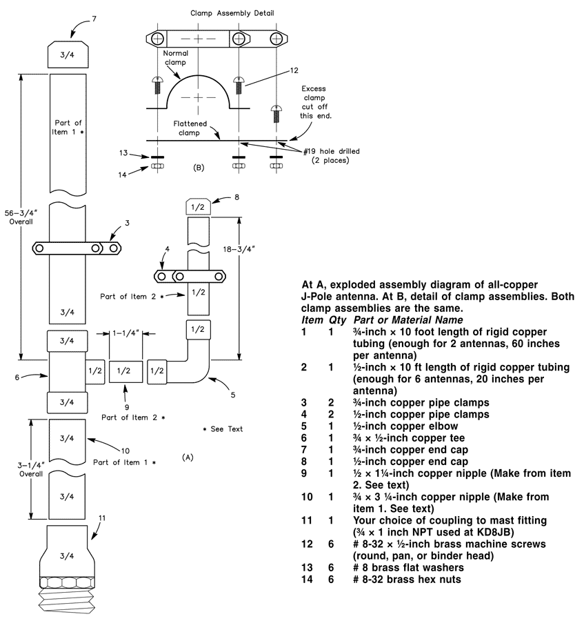
Cut the copper tubing to the lengths indicated. Item 9 is a 11/4-inch nipple cut from the 20-inch length of 1/2-inch tubing. This leaves 183/4 inches for the 1/4-matching stub. Item 10 is a 31/4-inch long nipple cut from the 60-inch length of 3/4-inch tubing. The 3/4-wave element should measure 563/4-inches long.

Remove burrs from the ends of the tubing after cutting, and clean the mating surfaces with sandpaper, steel wool, or emery cloth. After cleaning, apply a very thin coat of flux to the mating elements and assemble the tubing, elbow, tee, end caps and stubs. Solder the assembled parts with a propane torch and rosin-core solder. Wipe off excess solder with a damp cloth, being careful not to burn yourself.

The copper tubing will hold heat for a long time after you’ve finished soldering. After soldering, set the assembly aside to cool. Flatten one each of the 1/2-inch and 3/4-inch pipe clamps. Drill a hole in the flattened clamp as shown. Assemble the clamps and cut off the excess metal from the flattened clamp using the unmodified clamp as a template. Disassemble the clamps. Assemble the 1/2-inch clamp around the 1/4-wave element and secure with two of the screws, washers, and nuts as shown. Do the same with the 3/4-inch clamp around the 3/4-wave element. Set the clamps initially to a spot about 4 inches above the bottom of the “J” on their respective elements. Tighten the clamps only finger tight, since you’ll need to move them when tuning.

Tuning
The J-Pole can be fed directly from 50-ohm coax through a choke balun (3 turns of the feed coax rolled into a coil about 8 inches in diameter and held together with electrical tape). Before tuning, mount the antenna vertically, about 5 to 10 feet from the ground. A short TV mast on a tripod works well for this purpose.

When tuning VHF antennas, keep in mind that they are sensitive to nearby objects—such as your body. Attach the feed line to the clamps on the antenna, and make sure all the nuts and screws are at least finger tight. It really doesn’t matter to which element (¾-wave element or stub) you attach the coaxial center lead.

Tune the antenna by moving the two feed-point clamps equal distances a small amount each time until the SWR is minimum at the desired frequency. The SWR will be close to 1:1.

Final Assembly
The final assembly of the antenna will determine its long-term survivability. Perform the following steps with care. After adjusting the clamps for minimum SWR, mark the clamp positions with a pencil and then remove the feed line and clamps. Apply a very thin coating of flux to the inside of the clamp and the corresponding surface of the antenna element where the clamp attaches. Install the clamps and tighten the clamp screws.

Solder the feed line clamps where they are attached to the antenna elements. Now, apply a small amount of solder around the screw heads and nuts where they contact the clamps. Don’t get solder on the screw threads! Clean away excess flux with a non-corrosive solvent.

After final assembly and erecting/mounting the antenna in the desired location, attach the feed line and secure with the remaining washer and nut. Weather-seal this joint with RTV.

Source: The ARRL Antenna Handbook

Thursday, 20 October 2011

My D-Star Adventure, by Bruce Given VE2GZI

Having always being interested in computers and all things digital is probably the reason that I started to look at the D-Star a couple of years ago , but the reports of bad audio and basically no repeaters in Montreal in English pretty much kept me away from purchasing a digital rig.

But last May, while in Dayton, I finally succumbed and purchased a Icom ID-880H as I had heard that VE2RM and VE2REX would be putting up repeaters (Thanks Cliff). So I brought it and due to family and work it pretty much stayed in its box on the shelf till late September, early October.

That just happened to be the time that ICOM was seeding the Canadian Market with free repeater offers to clubs.

VE2RM got one and finally got it installed, previous to this they had a mini style repeater but no gateway (internet access) so it was pretty limited.

As most of the comments that I had heard and Youtube videos that I looked at talked about the radios being pig’s to program, I thought that I would get a cable and download the software.
Well the ICOM software is OK but I am sure glad that I didn’t pay for it. Besides the fact that there is no manual, let’s just say that it’s not that intuitive (and that’s being nice). I finally got to grips with it and got the essentials programmed into the rig the standard URCALL ,MYCALL, Rpt1 and Rpt2 and yes don’t forget the 8th character it’s got to be the 8th on the call sign for the repeater or the thing will not work.

Well all sorted and I hit the PTT and I was on the air my first QSO on D-Star was Nick VE2HOT it’s fun it’s digital and it’s the future.

Having said that I have heard all the grumbling from other members of the Ham fraternity that the codec is no good and it sounds horrible and why is the band width so small and the why is the codec  closed and not open source...

I could go on but really what matters is it`s Amateur radio, it`s not funded by a well know or huge corporation, it`s mostly a open standard and that`s the spirit of Amateur radio

Get out and try it have fun with it experiment that`s what amateur radio is about, if anybody wants help I am very happy to help.

Digitally yours,
Bruce VE2GZI

Saturday, 15 October 2011

A short presentation of D-STAR (Digital Smart Technologies for Amateur Radio)


D-STAR (Digital Smart Technologies for Amateur Radio) is a digital voice and data protocol specification developed as the result of research by the Japan Amateur Radio League (JARL) to investigate digital technologies for Amateur Radio in 2001. While there are other digital on-air technologies being used by amateurs that were developed for other services, D-STAR is one of the first on-air protocols to be widely deployed and sold by a major radio manufacturer that is designed specifically for amateur service use.

D-STAR transfers both voice and data via a data stream over the 2 meter (VHF), 70 cm (UHF), and 23 cm (1.2 GHz) Amateur Radio bands either simplex or via repeater. One of the interesting features about the D-STAR protocol is the fact the system uses Amateur Radio call signs not only as an identifier, but for signal routing.

In the most common configuration, the most vital part of a D-STAR system is the gateway server, which networks a single system into a D-STAR network via a trust server. The trust server provides a central, master database to look up users and their  associated system. Allowing Amateur Radio operators to respond to calls made to them, regardless of their location on the D-STAR Network. While almost all documentation references the Internet as the connection point for a network, any IP network connectivity will work, depending on signal latency. Additionally, D-STAR can provide a zero infrastructure support system utilizing point-to-point “backbone” 10 GHz connections. Currently, the global D-STAR trust server is maintained by a group of dedicated D-STAR enthusiasts from Dallas, Texas — the Texas Interconnect Team.

The D-STAR protocol specifies two modes; Digital Voice (DV) and Digital Data (DD). In the protocol, the DV mode provides both voice and low speed data channel on 2 meters, 70 cm and 23 cm over a 4800-bit/s data stream. In the protocol, the DV mode uses a data rate of 4800 bit/s. This data stream is broken down to three main packages: voice, forward error correction (FEC) and data.
The largest portion of the data stream is the voice package, which is a total of 3600 bits/s with 1200 bits/s dedicated to forward error correction, leaving 1200 bit/s for data. This additional data contains various data flags as well as the data header, leaving about 950 bit/s available for either GPS or serial data. This portion of the data stream does not provide any type of error  correction, which has been overcome by implementing error correction in the application software.

While there are various techniques of encoding and transporting a DV signal, the focus of D-STAR’s design was the most efficient way to conserve RF spectrum. While D-STAR’s "advertised" occupied bandwidth is 6.25 kHz, tests reveal a band plan of 10 kHz spacing is adequate to  incorporate the D-STAR signal as well as provide space for channel guards.

In addition to DV mode, the D-STAR protocol outlines the high speed Digital Data (DD) mode. This higher speed data, 128 kbit/s, is available only on the 23 cm band because it requires an  advertised 130 kHz bandwidth, only available at 23 cm in world-wide band plans. Unlike the DV mode repeaters, the DD mode module operates as an "access point" operating in half duplex, switching quickly on a single channel. As with the DV mode, there is a portion of the data stream used for signal identification with the data header as well as various system flags and other D-STAR related items. Once this portion of the data stream is taken into consideration, the 128 kbit/s is reduced to approximately 100 kbit/s — still more than double a dial-up connection speed with significant range.
Another consideration is the data rate specified at 128 kbit/s is the gross data rate. Therefore, the system developers are challenged by the area coverage/potential user issue. Meaning the higher the elevation of the system, the more potential users and the slower the system will become as all the users split the data bandwidth.
Finally, there is an issue from the days of packet radio. While technically, the opportunity for "hidden transmitter" issues does exist and collisions do occur, the T/R switching is very fast and this effect is handled by TCP/IP as it is for WiFi access points.

The simplex channel eliminates the need for duplexers at a repeater site if only the DD mode system is installed. It is still recommended to have filtering, such as a band-pass filter, in place to reduce possible  interference from other digital sources close to the 23 cm band as well as reduce RF overload from nearby RF sources. While some DD Mode system owners would like more sensitivity or more output power (10 W), at the time of print, no manufacturer has developed pre-amps or RF power amplifiers with an adequate T/R switching time to boost the signals.

Radios currently providing DV mode data service use a serial port for low-speed data (1200 bit/s), while the DD mode radio offers a standard Ethernet connection for high speed (128 kbps) connections, to allow easy interfacing with computer equipment. The DD-mode Ethernet jack allows two radios to act as an Ethernet bridge without any special software support required. This allows standard file sharing, FTP, TELNET, HTTP/ Web browsing, IRC chat or even Remote Desktop Connections to function as if connected by wire.

In a Gateway configuration, ALL users must be registered in the network. This provides the DD mode sysop a layer of authorization, meaning that if someone wants to use a DD-mode system, and they have not received authorization to use the gateway, their DD mode access will be denied. Any gateway registered user, on the common network, can use any DD-mode system, even if the  registration was not made on that system. While we are not able to use encryption in the Amateur Radio service, security can be implemented in standard software or consumer routers and firewalls.

A D-STAR repeater system consists of at least one RF module and a controller. While any combination of RF modules can be installed, typically a full system includes the three voice modules (2 m, 70 cm and 23 cm) and the 23 cm DD mode module.
A computer with dual Ethernet ports, running the Gateway software is required for Internet access to the global network. An additional server, as shown in the diagram, can be incorporated for local hosting of e-mail, chat, FTP, Web and other services. In a D-STAR system installation, the standard repeater components (cavities, isolators, antennas, etc.) are not shown but are required as with any analog system. Some groups have removed analog gear and replaced it with D-STAR components on the same frequency with no additional work beyond connecting the power and feed lines.