Showing posts with label digital radio. Show all posts

Thursday, 13 December 2012

Re-introduction of the DVRPTR_V1 Boards :: Press Release


Re-introduction of the DVRPTR_V1 Boards as a Low Cost Solution for Building Hotspots, Repeaters and Stand-alone Repeaters

FOR IMMEDIATE RELEASE

Montreal, December 7, 2012

Increased demand for a low-cost solution for building hotspots and repeaters, encouraged the re-introduction of the proven DVRPTR_V1 boards as a viable alternative to the existing offering.

These robust and low-cost boards are a great incentive for many hams to start experimenting with the digital modes.

The "new" DVRPTR_V1 boards will be assembled, individually tested and shipped worldwide from Montreal, Canada. Depending on the demand, the boards are expected to be ready for shipping by the end of February 2013.

" As creator of the original DV-RPTR V1 project (name, hardware and firmware) I'm happy that this project will continue..." said Jan Alte, DO1FJN. "This board is not perfect - I know, but it is a reliable, low-price solution for building hotspots, repeaters and stand-alone repeaters. I will resume my firmware development and I hope to find more dedicated specialists that can help improve the board's open source firmware."

Bruce Given, VE2GZI, hardware engineer with over 20 years of experience in the electronic components business, will coordinate the production and logistics efforts of this project.

"My top priority is to promote this great product in the amateur community and to offer it bundled with timely delivery, excellent service and technical support" said Bruce Given, VE2GZI.

Contact information:
Bruce Given, VE2GZI, bruce.given@gmail.com
http://groups.yahoo.com/group/DVRPTR_V1/

Sunday, 10 June 2012

My Modular Approach To HF Digital Interfacing :: by Steve Perron VA2PSL


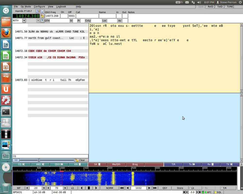
While I do have another interface I built a few years back on a PC board with isolation transformers, RS232 to PTT, VOX PTT and even a sound card to Morse keying interface, I prefer to use a more modular approach to interfacing HF transceivers to a sound card to use the various digital modes. Because getting on HF digital has been as simple as hooking up your transceiver to the sound card of your computer, there's been a wide range of new applications and modes available to experiment with over the past decade. I started playing around with PSK31 when it came out in the late 90s, and my first interface was a simple cable from my sound card to the back of my Icom 735, no audio isolation. I also used an RS232 to PTT that was made with a resistor and the perennial 2N2222a. It worked great, so keep this in mind.
Now, my current little HF rig, the FT-857 is not as simple to interface as some of the newer rigs like the Icom 7200 or the Kenwood TS590 which have built-in USB sound card and radio control, but it does provide a lot more functionality than my old 735. For starters, the radio has settings for audio gain when running digital, aka the back input/output on the rig. There's also a digital VOX and PTT through the CAT interface.

Part 1: The USB Serial Cable

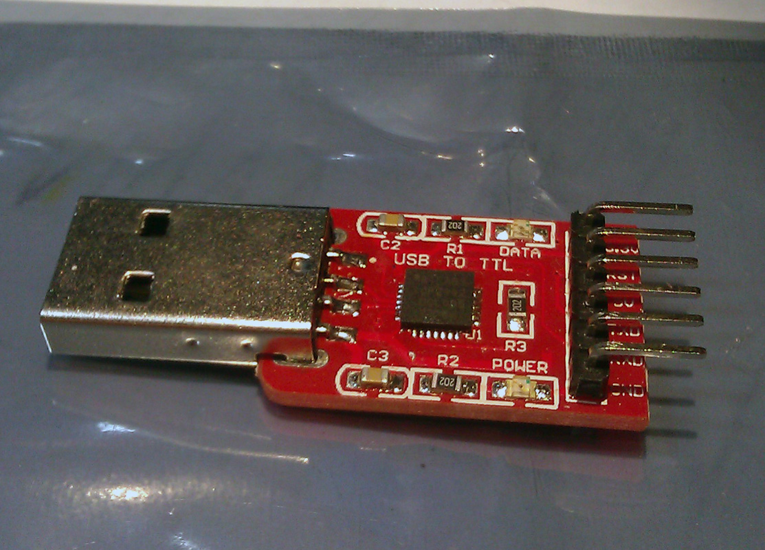
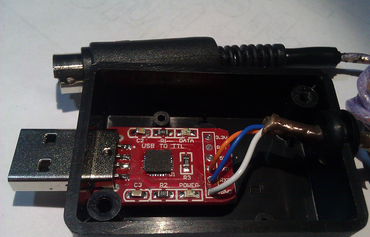
Almost all transceivers made since the mid 80s have some form of serial port interface which provide for the control of the mode, frequency, PTT and on the newer rigs, a lot more. If you've played with Ham Radio Deluxe, you actually get a pretty complete panel to control your radio. Most plans you'll find online or in the magazines are simple RS232 voltage converters (+12V to -12V) to TTL (0V to +5V). You can order USB cables from various sources, but they tend to use the Prolific PL2303 chip which has been cloned by Chinese chip manufacturers. Prolific has added an anti-clone feature in their drivers which is why all these USB programming cables from China do not work with the latest drivers. I had a CAT (Yaesu's name for this interface) USB cable with the PL2303 clone, and it simply died on me. My new interface uses the CP2102 from Silicon labs. The drivers actually work, and you can pick up the ready-made modules on eBay for less than 3$. As I said earlier, quite a few software support the PTT functionality directly through this interface, including my favorite software, FLDIGI. FLDIGI is available on most operating systems, including Linux. So when running FLDIGI, I get both the control of the mode/frequency and the PTT using my simple USB to CAT interface. See the pictures below. All that is required on the Yaesu and Kenwood is for the RX/TX and GND to be connected to the connector on the back of the transceiver. If you're using an Icom transceiver, the RX and TX would be tied together, since the interface is half-duplex. My module did not follow the convention of RX->TX, TX->RX, but rather RX->RX and TX->TX, so please be aware. If it's not working for you, simply swap the wires around. In windows, the interface will be assigned a Com port. Under Linux, it will be /dev/ttyUSB0, when the 0 could be a different number if like me you have more than one USB-Serial cable attached.

Part 2: The Sound card Interface


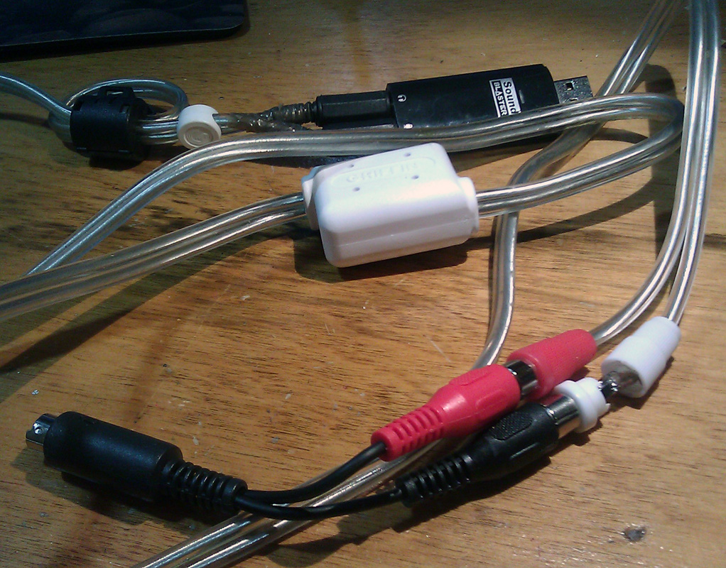
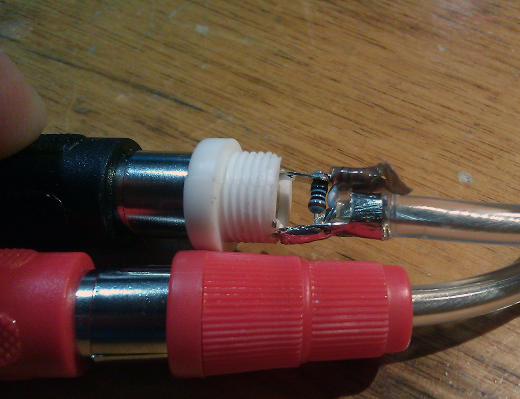
My audio interface is even simpler. I simply used half of an audio cable with female RCA jacks soldered to a mini-din8 on the ground, Audio in and Audio Out pins. I'm later going to add another RCA jack for the PTT line. My other cable is an eBay-special Griffin stereo isolation cable. While this cable is not available anymore, any similar cable/interface could be used. I installed 3.5mm stereo plugs on one end, and I replaced the male RCA on the other end so that I could make a simple voltage divider to reduce the audio amplitude of the signal so it would be more compatible with most transceivers out there. It's not required on the FT857 thanks to the programmable audio gain, but I want my cable to be compatible with most rigs. The voltage divider is simply two resistors, 10k and 1k, soldered inside the RCA jack going to the audio in of the transceiver. You can see that I'm also using a USB sound card. This is mostly to avoid transmitting operating system sounds and some laptops lack any form of audio input.


Part 3: The Optional RS232 PTT Interface

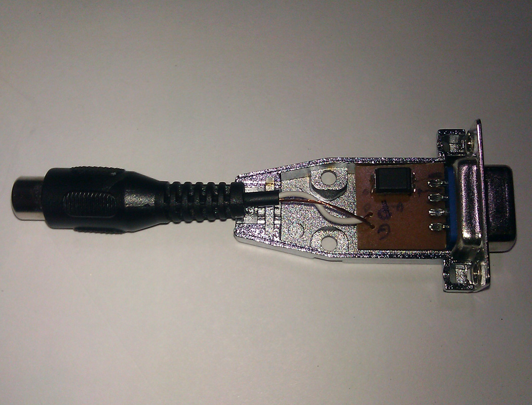
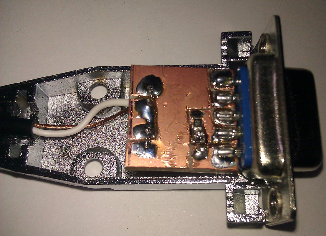
This interface is simply an opto-isolator inside a DB9 housing. It can be used with any serial port, including most USB-Serial cables. The CP2102 module I discussed earlier lacks the required RTS or DTR signals. To keep the little PCB as simple as possible, I only use the DTR. The PCB was done freehand using a Dremel tool. You can find the schematic of the interface online or even in the ARRL handbook. This interface would be required if the software does not support CAT PTT, VOX is not available or undesirable. An example of this would be when running the UZ7HO sound card packet modem. There are numerous amateurs using APRS on HF with this modem. Alternatively, it could also be used as a software Morse keyer. N1MM and other logging software support this as well as the CW-daemon in Linux.


Part 4: Digital Modes Software and Random Ramblings

There are a few software I find more interesting. FLDIGI is the Swiss army-knife of digital modes. I'm only aware of one software that supports more different modes, MultiPSK, but I find it not user-friendly and it does not run on Linux. PSK Mail is a software than runs of top of FLDIGI and provides ARQ email throughout the world (Think Amtor, Pactor). Winmor is a modem that can be used with RMS Express to provide access to the Winlink 2000 system without an expensive SCS-PTC Pactor modem. While I would not rely on Winmor to do mission-critical emails, it can be useful to check your emails if you're in an area that does not have any other forms of coverage. Winmor is only available on Windows.
I don't recommend using the microphone jack unless your rig only has this input. The microphone jack has much more gain than the digital port at the back of your radio and this can lead to over-modulation. Most commercially made interfaces simply regroup all these functionalities in a pretty box. The wildly popular Signalink interface from Tigertronics is a USB soundcard with audio isolation and a VOX setup. The VOX would be redundant on my transceiver, and I prefer not to use VOX, as it tends to mangle most ARQ modes, like HF packet. The first few milliseconds of the transmission would be missing because VOX always has latency.

Sunday, 27 May 2012

VA2CYH DMR Repeater is back on the air

Great news for the MotoTRBO enthusiasts in Quebec!

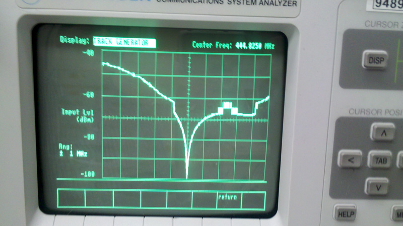
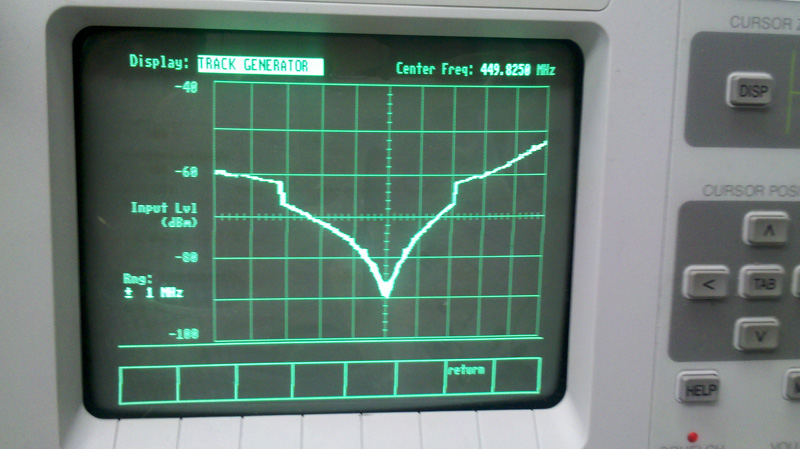
The VA2CYH DMR repeater is operating again, in test mode, on 449.825 MHz (minus) from its location in Covey Hill, Qc.
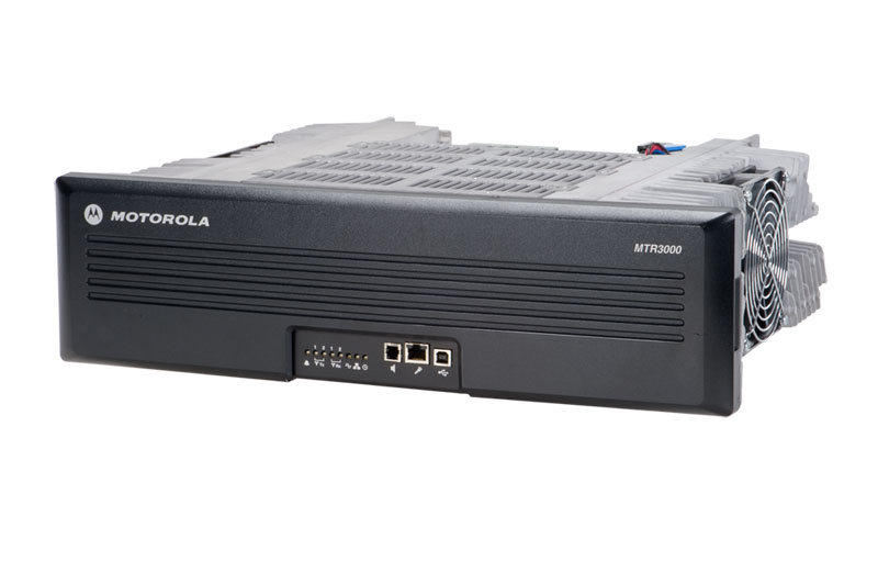
Powered by the Motorola MTR3000 Digital/Analog repeater, the system runs for now in low power mode (40W) until Alain VA2SPB receives the new duplexer. Once the new duplexer is in place, the repeater will put close to 100W in a 8 bay antenna.
As you can see from the enclosed images, Claude VE2YI did a great job tuning the small Sinclabs duplexer.
Click to enlarge
Click to enlarge

Thursday, 19 January 2012

Electra Proximity Payload :: SDR ( software-defined radio) by NASA's Jet Propulsion Laboratory

Today, I stumbled upon a little SDR (software-defined radio) package with a big responsibility.

Electra Proximity Payload, is a software-defined radio defined and implemented by the Jet Propulsion Laboratory for use between spacecraft. It is typically used by a lander to communicate with an orbiter that can then communicate with Earth.

Click here to download the complete specifications in PDF format

Sources: Wikipedia and NASA

Thursday, 20 October 2011

My D-Star Adventure, by Bruce Given VE2GZI

Having always being interested in computers and all things digital is probably the reason that I started to look at the D-Star a couple of years ago , but the reports of bad audio and basically no repeaters in Montreal in English pretty much kept me away from purchasing a digital rig.

But last May, while in Dayton, I finally succumbed and purchased a Icom ID-880H as I had heard that VE2RM and VE2REX would be putting up repeaters (Thanks Cliff). So I brought it and due to family and work it pretty much stayed in its box on the shelf till late September, early October.

That just happened to be the time that ICOM was seeding the Canadian Market with free repeater offers to clubs.

VE2RM got one and finally got it installed, previous to this they had a mini style repeater but no gateway (internet access) so it was pretty limited.

As most of the comments that I had heard and Youtube videos that I looked at talked about the radios being pig’s to program, I thought that I would get a cable and download the software.
Well the ICOM software is OK but I am sure glad that I didn’t pay for it. Besides the fact that there is no manual, let’s just say that it’s not that intuitive (and that’s being nice). I finally got to grips with it and got the essentials programmed into the rig the standard URCALL ,MYCALL, Rpt1 and Rpt2 and yes don’t forget the 8th character it’s got to be the 8th on the call sign for the repeater or the thing will not work.

Well all sorted and I hit the PTT and I was on the air my first QSO on D-Star was Nick VE2HOT it’s fun it’s digital and it’s the future.

Having said that I have heard all the grumbling from other members of the Ham fraternity that the codec is no good and it sounds horrible and why is the band width so small and the why is the codec  closed and not open source...

I could go on but really what matters is it`s Amateur radio, it`s not funded by a well know or huge corporation, it`s mostly a open standard and that`s the spirit of Amateur radio

Get out and try it have fun with it experiment that`s what amateur radio is about, if anybody wants help I am very happy to help.

Digitally yours,
Bruce VE2GZI

Sunday, 16 October 2011

Project 25 (P25) :: Short Presentation

What is Project 25?
Project 25 is a digital radio system designed specifically for public safety applications by police, fire and medical services. It will also find applications with utility operators and other government agencies.
With interoperability and maximizing radio spectrum efficiency as fundamental requirements, Project 25 Phase I uses digital voice encoding to reduce the required bandwidth for speech transmission to 12.5 kHz, while simultaneously maintaining backward compatibility and inter-operation with the existing 25 kHz analog FM systems. A further development of the specification will reduce the required transmission bandwidth for voice down to 6.25 kHz, thus freeing up more spectrum for future use.
The Project 25 specifications are available in the public domain, enabling multiple equipment vendors to compete for this market with the objective of reducing end user costs and providing interoperability both within and between user communities.

Project 25 features
Only some of the features that make Project 25 suitable for public safety use are given here.
Priority calling enables calls to be ranked in importance so that the system is always available for high priority traffic such as emergency calls. These are usually accessed from a single key push on the terminal.
Encryption prevents call interception and ensures that the communication is kept secure.
Call Alert and User ID are used to keep the user fully informed of the status of the communication channel in use.
Group Calling allows a message to be broadcast to all other members of a specific group.
Affiliation enables the members of the group to change to meet operational requirements. This can be done over the air allowing dynamic reconfiguration of talk groups. Encryption keys can also be changed in this way to retain security within the talk groups.

Interoperability
User groups can be dynamically reconfigured over the air so that communications can be maintained between all those required to be in attendance. Cross-Band Repeaters can also be used when agencies are allocated different frequency plans.

Spectrum Efficiency
Existing analog technology supports voice traffic in a bandwidth of 25 kHz. The use of digital technology allows the same voice quality to be transmitted in a 12.5 kHz bandwidth for Project 25 Phase 1. In the future a more complex modulation will allow the same voice information to be transmitted in a 6.25 kHz bandwidth.

Basic System Components
Mobile terminals, either vehicular mounted or portable, communicate in normal mode to the Base repeaters. These are interconnected with a land line or microwave link to the main switch in the base station. Depending on system complexity, a Trunking controller may be included to provide more efficient use of spectrum if the traffic level demands it. Interfaces to a dispatch console complete the basic system and a PSTN interconnect can also be provided.
Additionally, the terminals have a talk around facility which allows direct communication between mobiles without the need for the infrastructure.

Trunking
Trunking gives a significant increase in capacity as well as having the capability to build a geographically larger network. Backwards compatibility with the existing analog systems enables Project 25 to use existing trunked infrastructure such as the Smartnet™ and Smartzone™ systems from Motorola.
The Project 25 standard also has its own defined trunked mode for implementation of a totally digital network.

Analog vs. Digital
In order to obtain an acceptable voice quality using analog FM modulation, a channel bandwidth approaching 25 kHz is required. Additionally, signaling to maintain the radio link and provide call management occupies some of the available resource.
The use of a high level modulation called Continuous 4 level FM (C4FM) enables 9600 bits to be transmitted in a 12.5 kHz channel. This enables error correction information to be transmitted along with the
voice signal and signaling information. The error correction is able to correct for small errors in the received signal thus providing a more robust service without any of the background hiss that you hear on analog systems as they get near the edge of range.
The Phase II implementation will use a further increase in modulation complexity to support the same 9600 bits in a 6.25 kHz channel.

Analog to Digital Conversion
In a digital system the voice is encoded into a bit stream by a device called a Vocoder. Various techniques are used to do this and the one selected for use in Project 25 is called an Improved Multi-Band Excitation (IMBE) Vocoder. This uses complex algorithms to reduce each 20ms of speech to 88 bits of information to be transmitted over the radio link. The receiving device reverses the process to produce 20ms of analog speech signal.
The IMBE Vocoder converts a 3100 Hz audio band (300-3400 Hz) to a 4400 bps digital signal.

Modulation
The Phase I implementation of Project 25 uses a modified form of four level FM as its modulation technique. The information is transmitted in the form of a digital data stream and is modulated as symbols.
Each symbol type is determined by two bits of data giving four symbol types in total. The symbol types are represented by a particular FM deviation applied to the carrier. The modulation is characterized as being complex because the deviation is not symmetrical about the carrier as you would expect in a conventional FM system although it is of fixed amplitude.
Compatible Quadrature Phase Shift Keying (CQPSK) has been considered as a possibility for Phase II modulation. With CQPSK, each symbol is identified by the phase change from the previous symbol. This is one of a family of modulations generally grouped under the term of linear modulation in which both the phase and the amplitude of the
signal vary from symbol to symbol.

Security flaws
According to an article published in The Wall Street journal in 2011, researchers from the University of Pennsylvania overheard conversations that included descriptions of undercover agents and confidential informants, plans for forthcoming arrests and information on the technology used in surveillance operations. It was determined that the messages sent over the radios are sent in segments, and blocking just a portion of these segments can result in the entire message being jammed. Their study also shows that the radios can be effectively jammed (single radio, short range) using a highly modified pink electronic child’s toy. With other systems, jammers have to expend a lot of power to block communications, but the P25 radios allow jamming at relatively low power, enabling the researchers to prevent reception using a $30 toy pager.

The report was presented at the 20th Usenix Security Symposium in San Francisco in August 2011. The report noted a number of security flaws in the Project 25 system, some specific to the way it has been implemented and some inherent in the security design.

The report did not find any breaks in the P25 encryption, however they observed large amounts of sensitive traffic being sent in the clear due to implementations problems. They found switch markings for secure and clear modes difficult to distinguish (∅ vs. o). This is exacerbated by the fact that P25 radios when set to secure mode continue to operate without issuing a warning if another party switches to clear mode. In addition, the report authors said many P25 systems change keys too often, increasing the risk that an individual radio on a net may not be properly keyed, forcing all users on the net to transmit in the clear to maintain communications with that radio.

One design choice was to use lower levels of error correction for portions of the encoded voice data that is deemed less critical for intelligibility. As a result bit errors may be expected in typical transmissions, and while harmless for voice communication, the presence of such errors force the use of stream ciphers, which can tolerate bit errors, and prevents the use of a standard technique, message authentication codes (MACs), to protect message integrity from stream cipher attacks. The varying levels of error correction are implemented by breaking P25 message frames into subframes. This allows an attacker to jam entire messages by transmitting only during certain short subframes that are critical to reception of the entire frame. As a result an attacker can effectively jam Project 25 signals with average power levels much lower that the power levels used for communication. Such attacks can be targeted at encrypted transmissions only, forcing users to transmit in the clear.

Because Project 25 radios are designed to work in existing two-way radio frequency channels, they cannot use spread spectrum modulation, which is inherently jam-resistant. An optimal spread spectrum system can require a effective jammer to use 1000 times as much power (30 db more) as the individual communicators. According to the report, a P25 jammer could effectively operate at 1/25th the power than the communicating radios. The authors developed a proof-of-concept jammer using a Texas Instruments CC1110 single chip radio, found in an inexpensive toy.

Saturday, 15 October 2011

A short presentation of D-STAR (Digital Smart Technologies for Amateur Radio)


D-STAR (Digital Smart Technologies for Amateur Radio) is a digital voice and data protocol specification developed as the result of research by the Japan Amateur Radio League (JARL) to investigate digital technologies for Amateur Radio in 2001. While there are other digital on-air technologies being used by amateurs that were developed for other services, D-STAR is one of the first on-air protocols to be widely deployed and sold by a major radio manufacturer that is designed specifically for amateur service use.

D-STAR transfers both voice and data via a data stream over the 2 meter (VHF), 70 cm (UHF), and 23 cm (1.2 GHz) Amateur Radio bands either simplex or via repeater. One of the interesting features about the D-STAR protocol is the fact the system uses Amateur Radio call signs not only as an identifier, but for signal routing.

In the most common configuration, the most vital part of a D-STAR system is the gateway server, which networks a single system into a D-STAR network via a trust server. The trust server provides a central, master database to look up users and their  associated system. Allowing Amateur Radio operators to respond to calls made to them, regardless of their location on the D-STAR Network. While almost all documentation references the Internet as the connection point for a network, any IP network connectivity will work, depending on signal latency. Additionally, D-STAR can provide a zero infrastructure support system utilizing point-to-point “backbone” 10 GHz connections. Currently, the global D-STAR trust server is maintained by a group of dedicated D-STAR enthusiasts from Dallas, Texas — the Texas Interconnect Team.

The D-STAR protocol specifies two modes; Digital Voice (DV) and Digital Data (DD). In the protocol, the DV mode provides both voice and low speed data channel on 2 meters, 70 cm and 23 cm over a 4800-bit/s data stream. In the protocol, the DV mode uses a data rate of 4800 bit/s. This data stream is broken down to three main packages: voice, forward error correction (FEC) and data.
The largest portion of the data stream is the voice package, which is a total of 3600 bits/s with 1200 bits/s dedicated to forward error correction, leaving 1200 bit/s for data. This additional data contains various data flags as well as the data header, leaving about 950 bit/s available for either GPS or serial data. This portion of the data stream does not provide any type of error  correction, which has been overcome by implementing error correction in the application software.

While there are various techniques of encoding and transporting a DV signal, the focus of D-STAR’s design was the most efficient way to conserve RF spectrum. While D-STAR’s "advertised" occupied bandwidth is 6.25 kHz, tests reveal a band plan of 10 kHz spacing is adequate to  incorporate the D-STAR signal as well as provide space for channel guards.

In addition to DV mode, the D-STAR protocol outlines the high speed Digital Data (DD) mode. This higher speed data, 128 kbit/s, is available only on the 23 cm band because it requires an  advertised 130 kHz bandwidth, only available at 23 cm in world-wide band plans. Unlike the DV mode repeaters, the DD mode module operates as an "access point" operating in half duplex, switching quickly on a single channel. As with the DV mode, there is a portion of the data stream used for signal identification with the data header as well as various system flags and other D-STAR related items. Once this portion of the data stream is taken into consideration, the 128 kbit/s is reduced to approximately 100 kbit/s — still more than double a dial-up connection speed with significant range.
Another consideration is the data rate specified at 128 kbit/s is the gross data rate. Therefore, the system developers are challenged by the area coverage/potential user issue. Meaning the higher the elevation of the system, the more potential users and the slower the system will become as all the users split the data bandwidth.
Finally, there is an issue from the days of packet radio. While technically, the opportunity for "hidden transmitter" issues does exist and collisions do occur, the T/R switching is very fast and this effect is handled by TCP/IP as it is for WiFi access points.

The simplex channel eliminates the need for duplexers at a repeater site if only the DD mode system is installed. It is still recommended to have filtering, such as a band-pass filter, in place to reduce possible  interference from other digital sources close to the 23 cm band as well as reduce RF overload from nearby RF sources. While some DD Mode system owners would like more sensitivity or more output power (10 W), at the time of print, no manufacturer has developed pre-amps or RF power amplifiers with an adequate T/R switching time to boost the signals.

Radios currently providing DV mode data service use a serial port for low-speed data (1200 bit/s), while the DD mode radio offers a standard Ethernet connection for high speed (128 kbps) connections, to allow easy interfacing with computer equipment. The DD-mode Ethernet jack allows two radios to act as an Ethernet bridge without any special software support required. This allows standard file sharing, FTP, TELNET, HTTP/ Web browsing, IRC chat or even Remote Desktop Connections to function as if connected by wire.

In a Gateway configuration, ALL users must be registered in the network. This provides the DD mode sysop a layer of authorization, meaning that if someone wants to use a DD-mode system, and they have not received authorization to use the gateway, their DD mode access will be denied. Any gateway registered user, on the common network, can use any DD-mode system, even if the  registration was not made on that system. While we are not able to use encryption in the Amateur Radio service, security can be implemented in standard software or consumer routers and firewalls.

A D-STAR repeater system consists of at least one RF module and a controller. While any combination of RF modules can be installed, typically a full system includes the three voice modules (2 m, 70 cm and 23 cm) and the 23 cm DD mode module.
A computer with dual Ethernet ports, running the Gateway software is required for Internet access to the global network. An additional server, as shown in the diagram, can be incorporated for local hosting of e-mail, chat, FTP, Web and other services. In a D-STAR system installation, the standard repeater components (cavities, isolators, antennas, etc.) are not shown but are required as with any analog system. Some groups have removed analog gear and replaced it with D-STAR components on the same frequency with no additional work beyond connecting the power and feed lines.