The curtain antenna is a dipole array, consisting of rows and columns of dipoles. The number of rows can be 1, 2, 3, 4 or 6; the number of columns is usually 2 or 4.
The curtain antenna is a high gain directional antenna, designed for medium and long range communications.
The dipoles are horizontally polarized and a reflector screen is placed behind the dipole array to provide a directive beam.
Curtain antennas are available in two sizes. A low-band array covers the 6, 7, 9 and 11 MHz bands and a high-band array covers the 11, 13, 15, 17 and 21 MHz bands (or 13-26 MHz bands).
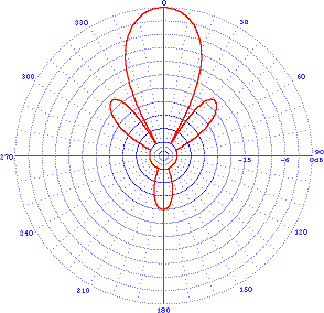
The number of dipole columns defines the azimuth beamwidth. For a 2-wide dipole array, the beamwidth is around 50°, for a 4-wide dipole array around 30°. The main beam can be slewed by 15 or 30° so that a maximum coverage of 90° can be achieved.
The number of dipole rows and the height of the lowest element above ground determine the elevation angle and consequently the distance of the service area. A 2-row high array has a typical takeoff angle of 20° and is used for medium range communications, while a 4-row high array has a typical takeoff angle of 10° and is used for long range communications.
The curtain antenna is designed for connection to a 300 ohm balanced open wire feeder.
 |
| Azimuth pattern |
 |
| Elevation pattern |
Technical Specifications
Azimuth pattern: directional
Frequency ranges: 6-26 MHz, up to 6 adjacent SW bands
Gain: 12.5-22.5 dBi
Input impedance: 300 ohm balanced
Polarization: horizontal
Power ratings: up to 500 kW carrier with 100% modulation

No comments:
Post a Comment