
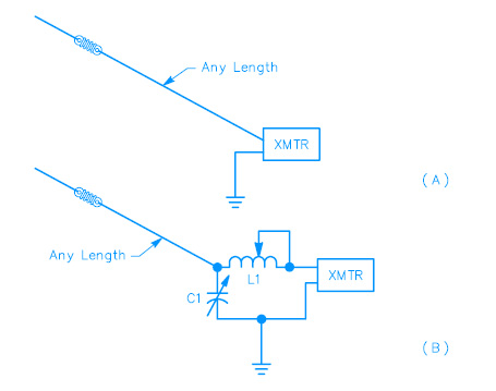
If you have installed a 28- or 50-MHz rotary beam, in many cases it may be possible to use the beam’s feed line as an antenna on the lower frequencies. Connecting the two wires of the feeder together at the station end will give a random length wire that can be conveniently coupled to the transmitter as in Fig 1. The rotary system at the far end will serve only to end-load the wire and will not have much other effect.
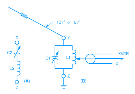
One disadvantage of all such directly fed systems is that part of the antenna is practically within the station, and there is a good chance that you will have some trouble with RF feedback. RF within the station can often be minimized by choosing a length of wire so that the low feed-point impedance at a current loop occurs at or near the transmitter. This means using a wire length of λ/4 (65 feet at 3.6 MHz, 33 feet at 7.1 MHz), or an odd multiple of λ/4 (3⁄4-λ is 195 feet at 3.6 MHz, 100 feet at 7.1 MHz).
Obviously, this can be done for only one band in the case of even harmonically related bands, since the wire length that presents a current loop at the transmitter will present a voltage loop at two (or four) times that frequency.
When you operate with a random-length wire antenna, as in Figs 1 and 2, you should try different types of grounds on the various bands, to see what gives you the best results. In many cases it will be satisfactory to return to the transmitter chassis for the ground, or directly to a convenient metallic water pipe. If neither of these works well (or the metallic water pipe is not available), a length of #12 or #14 wire (approximately λ/4 long) can often be used to good advantage. Connect the wire at the point in the circuit that is shown grounded, and run it out and down the side of the house, or support it a few feet above the ground if the station is on the first floor or in the basement. It should not be connected to actual ground at any point.
Source: ARRL Antenna Handbook 2010
No comments:
Post a Comment