 Cavity Resonators
Receiver desensing can be reduced by separating the transmitter and receiver antennas. But the amount of transmitted energy that reaches the receiver input must often be decreased even farther. Other nearby transmitters can cause desensing as well. A cavity resonator (cavity filter) can be helpful in solving these problems.
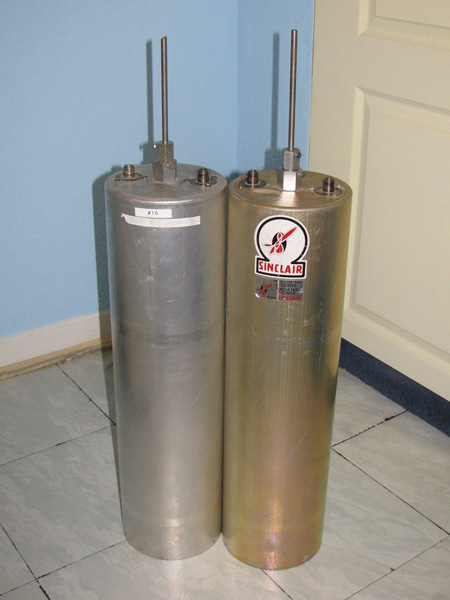
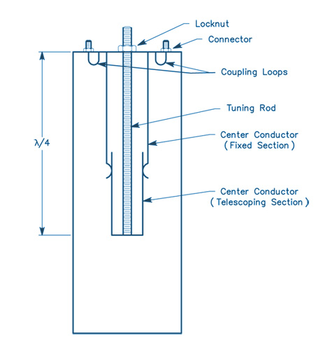
When properly designed and constructed, this type of resonator has very high Q. A cavity resonator placed in series with a transmission line acts as a band-pass filter. For a resonator to operate in series, it must have input and output coupling loops (or probes). A cavity resonator can also be connected across (in parallel with) a transmission line. The cavity then acts as a band-reject (notch) filter, greatly attenuating energy at the frequency to which it is tuned.
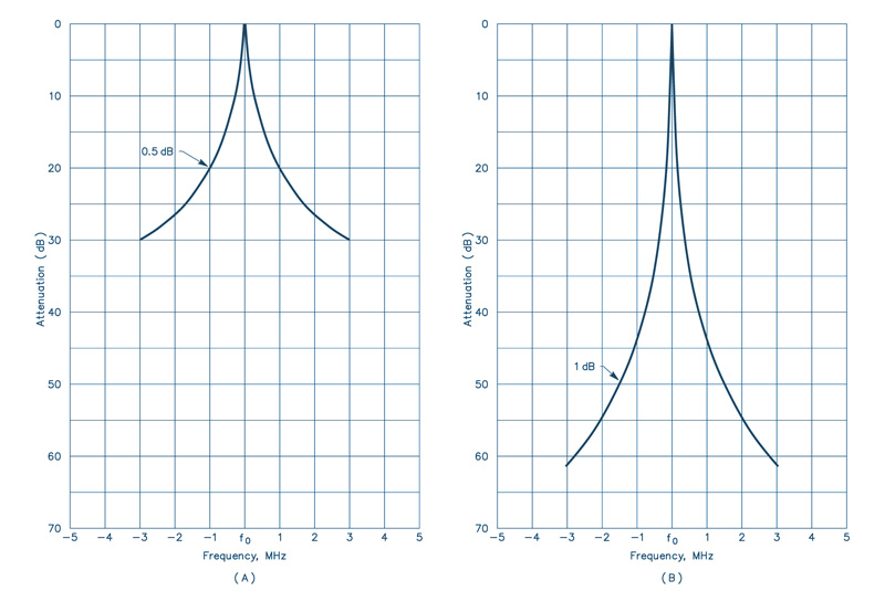
Only one coupling loop or probe is required for this method of filtering. This type of cavity could be used in the receiver line to "notch" the transmitter signal. Several cavities can be connected in series or parallel to increase the attenuation in a given configuration. The diagram below show the attenuation of a single cavity (A) and a pair of cavities (B).

The only situation in which cavity filters would not help is the case where the off-frequency noise of the transmitter was right on the receiver frequency. With cavity resonators, an important point to remember is that addition of a cavity across a transmission line may change the impedance of the system. This change can be compensated by adding tuning stubs along the transmission line.
Duplexers
Most amateur repeaters in the 144, 220 and 440 MHz bands use duplexers to obtain the necessary transmitter to receiver isolation. Duplexers have been commonly used in commercial repeaters for many years.
The duplexer consists of two high-Q filters. One filter is used in the feed line from the transmitter to the antenna, and another between the antenna and the receiver. These filters must have low loss at the frequency to which they are tuned while having very high attenuation at the surrounding frequencies. To meet the high attenuation requirements at frequencies within as little as 0.4% of the frequency to which they are tuned, the filters usually take the form of cascaded transmission line cavity filters.
These are either band-pass filters, or band-pass filters with a rejection notch which is tuned to the center frequency of the other filter. The number of cascaded filter sections is determined by the frequency separation and the ultimate attenuation requirements.
Duplexers for the amateur bands represent a significant technical challenge, because in most cases amateur repeaters operate with significantly less frequency separation than their commercial counterparts. Many manufacturers market high quality duplexers for the amateur frequencies.
Duplexers consist of very high-Q cavities whose resonant frequencies are determined by mechanical components, in particular the tuning rod. The rod is usually made of a material that has a limited thermal expansion coefficient (such as Invar). Detuning of the cavity by environmental changes introduces unwanted losses in the antenna system.
These can be broken into four major categories:
- Ambient temperature variation (which leads to mechanical variations related to the thermal expansion coefficients of the materials used in the cavity).
- Humidity (dielectric constant) variation.
- Localized heating from the power dissipated in the cavity (resulting from its insertion loss).
- Mechanical variations resulting from other factors (vibration, etc).
In addition, because of the high-Q nature of these cavities, the insertion loss of the duplexer increases when the signal is not at the peak of the filter response. This means, in practical terms, that less power is radiated for a given transmitter output power.
Also, the drift in cavities in the receiver line results in increased system noise figure, reducing the sensitivity of the repeater. As the frequency separation between the receiver and the transmitter decreases, the insertion loss of the duplexer reaches certain practical limits. At 144 MHz, the minimum insertion loss for 600 kHz spacing is 1.5 dB per filter.
Testing and using duplexers requires some special considerations (especially as frequency increases). Because duplexers are very high-Q devices, they are very sensitive to the termination impedances at their ports. A high SWR on any port is a serious problem, because the apparent insertion loss of the duplexer will increase, and the isolation may appear to decrease. Some have found that when duplexers are used at the limits of their isolation capabilities, a small change in antenna SWR is enough to cause receiver desensitization. This occurs most often under ice-loading conditions on antennas with open-wire phasing sections.
The choice of connectors in the duplexer system is important. BNC connectors are good for use below 300 MHz. Above 300 MHz, their use is discouraged because even though many types of BNC connectors work well up to 1 GHz, older style standard BNC connectors are inadequate at UHF and above.
Type N connectors should be used above 300 MHz. It is false economy to use marginal quality connectors. Some commercial users have reported deteriorated isolation in commercial UHF repeaters when using such connectors. The location of a bad connector in a system is a complicated and frustrating process. Despite all these considerations, the duplexer is still the best method for obtaining isolation in the 144 - 925 MHz range.
Source: the ARRL Antenna Handbook


No comments:
Post a Comment